128mm Wide Panel Bender Counterblade with 40mm Load-Bearing Height
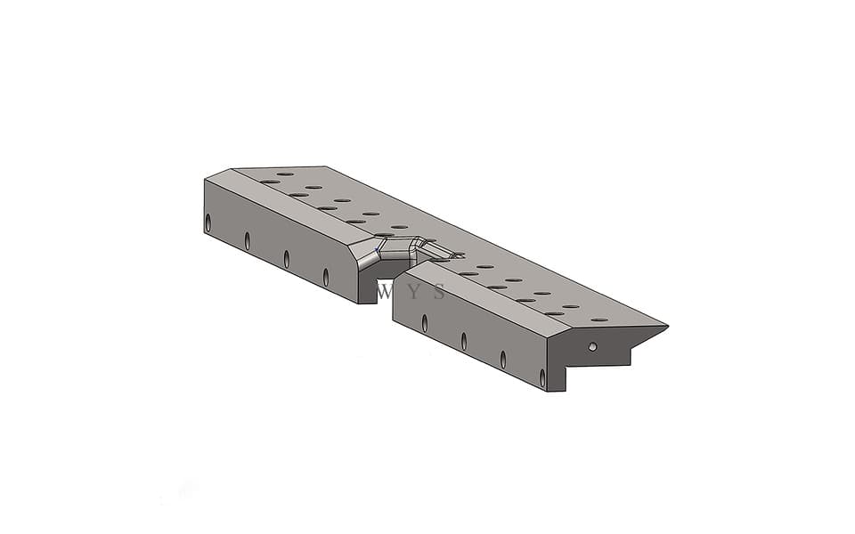
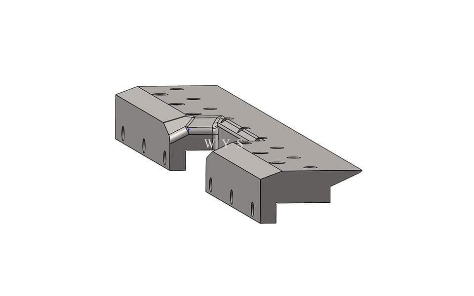
This precision panel bender counterblade provides fixed lower support for sheet metal during flexible panel bending. It measures 128 mm in width and 65 mm in height, with a 40 mm load-bearing section and a standard length of 1000 mm. Manufactured from 42CrMo alloy steel and through-hardened to HRC46–52, it works with the upper blankholder to secure the sheet and establish a stable, accurate bending line.
Please add the quotation and send it to us and get in touch with us immediately
- Global service 24/7
- Lowest price for all products
- Best quality with Production Process
- After-Sale Warranty
- Technical Support
Description
The 128mm Wide Panel Bender Counterblade is a precision fixed lower support tool designed for flexible panel benders and CNC panel bending centers. Installed beneath the sheet metal, it works with the upper blankholder to clamp, support and position the material along the programmed bending line.
The counterblade has an overall width of 128 mm, an overall height of 65 mm and a 40 mm load-bearing height. Its broad upper profile provides a stable supporting reference, while the stepped lower geometry creates the required mounting and machine clearance. The standard tool length is 1000 mm.
During the bending cycle, the upper blankholder moves toward the sheet and clamps it against this fixed counterblade. Once the material is secured, the upper or lower bending blade follows its CNC-controlled trajectory to form the projecting flange. The counterblade remains the stable lower reference for the complete operation.
Manufactured from 42CrMo alloy steel, the tool receives overall quenching and through-hardening to HRC46–52. Precision machining and controlled heat treatment help provide reliable structural strength, wear resistance and dimensional stability during repeated industrial panel bending cycles.
WYS Machinery manufactures standard and custom panel bender counterblades according to original tooling drawings, physical samples, machine mounting dimensions and customer-specific sheet metal applications.
Key Features
- Fixed lower support tool for flexible panel benders
- Overall width of 128 mm
- Overall height of 65 mm
- Load-bearing height of 40 mm
- Standard tool length of 1000 mm
- Manufactured from 42CrMo alloy steel
- Overall quenched and through-hardened
- Finished hardness of HRC46–52
- Wide supporting profile provides a stable sheet reference
- Stepped geometry provides mounting and operating clearance
- Multiple mounting holes support secure installation
- Works with the upper blankholder to clamp sheet metal
- Establishes a stable reference along the bending line
- Suitable for replacement and custom panel bender tooling
- Custom lengths, hole patterns and profiles available
Technical Specifications
| Specification | Value |
|---|---|
| Product Type | Counterblade / Fixed Lower Support Tool |
| Tooling Category | Panel Bender Tooling |
| Application | Flexible Panel Bender / CNC Panel Bending Center |
| Overall Width | 128 mm |
| Overall Height | 65 mm |
| Load-Bearing Height | 40 mm |
| Standard Length | 1000 mm |
| Material | 42CrMo Alloy Steel |
| Heat Treatment | Overall Quenching / Through-Hardening |
| Hardness | HRC46–52 |
| Installation Position | Fixed Lower Position |
| Main Function | Sheet Support and Bending-Line Reference |
| Mounting Method | Multiple Mounting Holes |
| Custom Length | Available |
| Custom Hole Pattern | Available |
| Custom Profile | Available |
| Machine Compatibility | According to Confirmed Interface Dimensions |
Function and Working Principle
The counterblade is one of the core components in a flexible panel bender tooling system. It provides a stable lower surface beneath the sheet and works with the blankholder to establish the bending line.
A typical panel bending cycle includes the following coordinated functions:
- The sheet is positioned by the panel bender.
- The blankholder moves toward the sheet.
- The material is clamped between the blankholder and counterblade.
- The counterblade supports the sheet from below.
- The upper or lower bending blade forms the projecting flange.
- The blankholder releases the sheet after the bend is completed.
Because the counterblade remains a stable lower reference, its dimensional accuracy, straightness and alignment directly influence sheet positioning and bending consistency.
Role in the Complete Panel Bender Tooling System
| Tooling Component | Main Function |
|---|---|
| Blankholder Tool | Clamps the sheet from above |
| Counterblade | Provides fixed lower support and bending reference |
| Upper Bending Blade | Produces controlled downward bending |
| Lower Bending Blade | Produces controlled upward bending |
| Special Panel Bender Tools | Support special clearance or forming requirements |
Unlike a conventional press brake lower die, a panel bender counterblade does not contain a traditional V-opening. It supports and secures the flat sheet while the bending blades move around the established bending line.
40mm Load-Bearing Height
The 40 mm load-bearing height refers to the vertical working section that receives and transfers the clamping and supporting forces during the panel bending cycle.
This reinforced section helps provide:
- Stable support beneath the sheet
- Reliable transfer of blankholding force
- Resistance to repeated clamping loads
- Consistent positioning along the bending line
- Structural rigidity across the working length
- Reduced risk of unwanted tool deformation
The required load-bearing section can be customized according to machine structure, tool installation and working conditions.
128mm Wide Support Profile
The 128 mm overall width provides a broad structural profile for stable support and tool installation. The tapered upper shape positions the working area near the bending line while the lower stepped structure provides clearance for mounting and surrounding machine components.
The profile can be modified according to:
- Machine installation dimensions
- Bending-line position
- Required working clearance
- Blankholder geometry
- Upper and lower blade trajectories
- Customer workpiece requirements
Continuous 1000mm Length
The standard length of this counterblade is 1000 mm. Consistent straightness and working height across the full length are important for uniform contact with the sheet and accurate alignment with the upper blankholder.
Alternative options may include:
- Customized continuous lengths
- Multiple matched tool sections
- Segmented counterblade construction
- Special end sections
- Custom mounting-hole arrangements
- Replacement sections for existing tooling systems
42CrMo Material and Heat Treatment
The counterblade is manufactured from 42CrMo alloy steel, selected for its combination of strength, toughness and resistance to repeated mechanical loading.
The complete tool undergoes overall quenching and through-hardening to HRC46–52. Controlled heat treatment helps provide:
- Consistent hardness across the tool body
- Reliable structural strength
- Resistance to deformation under clamping loads
- Improved wear resistance
- Dimensional stability during repeated operation
- A suitable balance between hardness and toughness
Critical supporting and mounting surfaces are machined according to the confirmed dimensional requirements.
Typical Applications
This fixed lower counterblade can support the production of sheet metal components for:
- Electrical cabinets
- Control enclosures
- Switchgear cabinets
- Elevator panels
- Metal doors and frames
- HVAC and ventilation panels
- Server and communication cabinets
- Storage cabinets and shelving
- Industrial equipment covers
- Stainless steel kitchen equipment
- Appliance housings
- Lighting enclosures
- Metal furniture components
- Box-shaped sheet metal parts
- Multi-sided panels
- Customized precision enclosures
Actual application capability depends on the panel bender model, complete tooling configuration, sheet material, material thickness and workpiece geometry.
Product Details and Manufacturing Quality
Each counterblade can be manufactured from an original technical drawing, machine-interface drawing or physical tooling sample.
The manufacturing and inspection process may include:
- 42CrMo raw-material verification
- CNC profile machining
- Mounting-hole machining
- Controlled overall quenching
- Through-hardening
- Precision machining after heat treatment
- Overall width and height inspection
- Load-bearing section verification
- Mounting-hole position inspection
- Straightness inspection
- Parallelism inspection
- Supporting-surface inspection
- Final dimensional and visual inspection
For a 1000 mm long counterblade, uniform working height and accurate alignment are essential for consistent contact with the blankholder.
Replacement Panel Bender Counterblades
This product can be supplied as a replacement counterblade, fixed lower blade or lower support tool for flexible panel benders with a matching mounting interface.
To confirm compatibility, customers should provide:
- Machine brand and model
- Original counterblade drawing
- Machine mounting dimensions
- Existing tool measurements
- Physical tool sample
- Mounting-hole pattern
- Installation photographs
- Required working length
Machine compatibility should be determined from the actual mounting dimensions and profile rather than assumed from the equipment brand alone.
Standard and Custom Panel Bender Tooling
WYS Machinery manufactures complete tooling solutions for flexible panel benders and CNC panel bending centers, including:
- Blankholder tools
- Counterblades
- Upper bending blades
- Lower bending blades
- Fixed lower support tools
- Blankholder segments
- Special panel bender tools
- Custom replacement tooling
Available counterblade customization options include:
- Overall width
- Overall height
- Load-bearing height
- Working profile
- Overall length
- Continuous or segmented construction
- Mounting-hole quantity and position
- Machine installation interface
- Heat-treatment requirements
- Surface treatment
- Special clearance geometry
Customers can provide original tooling drawings, physical samples or finished workpiece drawings. WYS offers free tooling evaluation and design support to help develop a suitable panel bender tooling solution.
Why Choose WYS Panel Bender Tooling
- Panel bender tools manufactured from drawings or samples
- High-strength 42CrMo alloy steel
- Controlled overall quenching and through-hardening
- Precision-machined supporting and mounting surfaces
- Custom continuous and segmented lengths
- Replacement counterblades for flexible panel benders
- Custom mounting holes and working profiles
- Complete blankholder, counterblade and bending blade solutions
- Dimensional inspection before delivery
- Customized packaging for long industrial tooling
Frequently Asked Questions
What is a counterblade on a panel bender?
A counterblade is the fixed lower support tool that works with the upper blankholder to clamp and position the sheet along the bending line.
Is a counterblade the same as a lower bending blade?
No. The counterblade provides fixed lower support. The lower bending blade moves against the projecting flange to produce an upward bend.
Is a counterblade the same as a press brake lower die?
No. A press brake lower die normally has a V-opening. A panel bender counterblade supports the sheet while the upper and lower bending blades perform the forming movements.
What does the 40 mm load-bearing height mean?
It refers to the vertical structural section that receives and transfers supporting and clamping forces during the panel bending cycle.
What material and hardness are used?
The counterblade is manufactured from 42CrMo alloy steel, overall quenched and through-hardened to HRC46–52.
Can the mounting-hole pattern be customized?
Yes. Hole quantity, hole position, overall length and installation profile can be manufactured according to original drawings or physical samples.
Can the counterblade be supplied in other lengths?
Yes. WYS can supply customized continuous lengths, matched sections or segmented counterblade configurations.
How is machine compatibility confirmed?
Compatibility is confirmed by checking the tool profile, mounting dimensions, hole pattern, working height and alignment requirements.