Return-Flange Box Bending with Swing Ear Tool
October 8, 2024
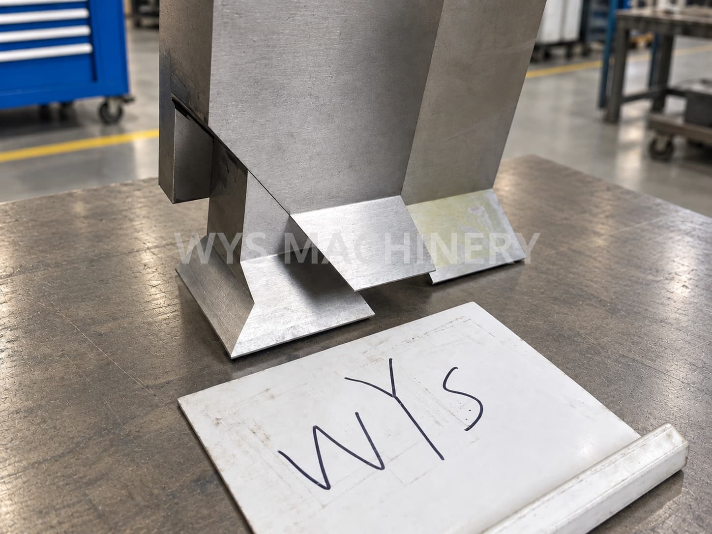
Return-Flange Box Bending with Swing Ear Tool
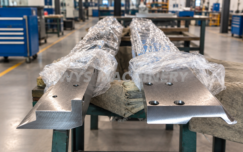
Complex box-shaped sheet metal parts often include inward or return flanges. During panel bending, these previously formed flanges may move very close to the upper tooling or bending blade, creating a risk of interference or collision.
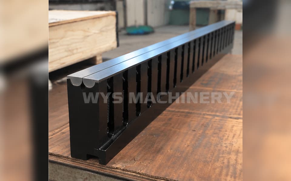
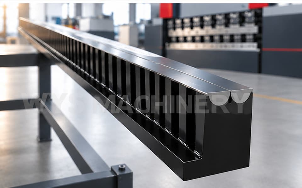
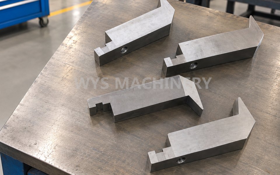
For this application, WYS Machinery designed and manufactured a complete panel bender tooling solution, including upper and lower tooling, bending blades and special Swing Ear Tools.
The swing ear structure provides the additional clearance required to complete complex inward-flange bending that may be difficult with conventional fixed tooling.
Why Is a Swing Ear Tool Used?
When forming a box or enclosure with an inward-facing flange, the formed section of the sheet can interfere with the upper tooling as the bending sequence progresses.
A Swing Ear Tool uses a movable ear structure to solve this clearance problem.
Depending on the workpiece geometry and bending direction, the tool can be designed with a Left Swing Ear or Right Swing Ear.
During the bending process, the swing ear moves outward to provide the required working profile. When the tooling retracts, the swing ear moves inward again, creating additional clearance for the already formed flange.
This movement helps prevent the sheet metal part from colliding with the upper tooling or upper bending blade.
Tooling Included in This Application
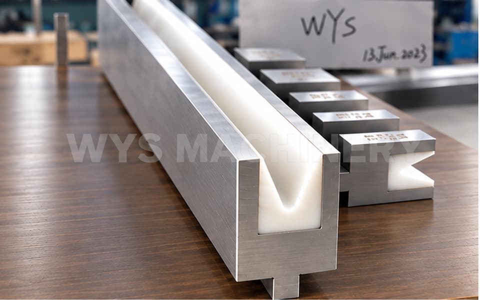
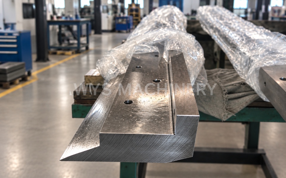
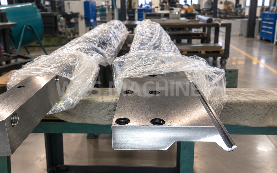
The tooling set shown in this application includes several types of panel bender tooling:
- Upper Clamping Tool – clamps and controls the sheet during the bending process.
- Lower Clamping Tool – supports and stabilizes the workpiece.
- Upper Bending Blade – performs the programmed bending movement.
- Swing Ear Tool – provides additional clearance for inward and return-flange bending.
The exact tooling combination depends on the geometry of the workpiece and the required bending sequence.
Left and Right Swing Ear Configurations
Swing ear tooling can be designed with either a Left Swing Ear or a Right Swing Ear according to the direction of the flange and the required clearance.
For more complex parts, different swing ear configurations can be incorporated into the tooling design to accommodate multiple bending directions and restricted areas.
The size, profile and movement of the swing ear should therefore be determined according to the actual workpiece rather than treated as a fixed standard configuration.
Typical Applications
This type of tooling solution is particularly suitable for:
- Return-flange box bending
- Inward flange bending
- Electrical cabinets and enclosures
- Sheet metal housings
- Deep box-shaped parts
- Parts with restricted tooling clearance
- Complex panel bending applications
- Components where conventional fixed tooling causes interference
Custom Panel Bender Tooling Based on Workpiece Drawings
The tooling shown in this application represents one customized solution rather than a fixed standard model.
Different workpieces may require different tooling heights, blade profiles, segment lengths, swing ear directions and clearance dimensions.
Customers can send WYS Machinery their workpiece drawings, material information, sheet thickness and machine tooling interface. Our engineering team can analyze the bending sequence, identify possible collision areas and design a suitable tooling solution.
This drawing-based approach is especially important for complex box bending, return-flange and inward-flange applications, where successful forming depends not only on the tooling dimensions but also on the relationship between the tooling, workpiece geometry and bending sequence.
How Does a Swing Ear Tool Prevent Collision During Panel Bending?
A swing ear tool uses a movable left or right ear that extends to provide the required tooling profile during bending and retracts inward when additional clearance is needed. This allows inward or return flanges to pass the upper tooling more safely, reducing the risk of interference during complex box bending.