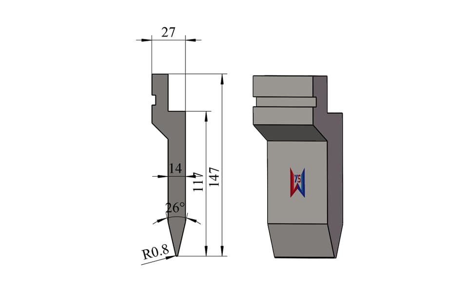
26° R0.8 Hemming Pre-Bending Press Brake Upper Punch – 147 mm Height, 117 mm Working Height, 80 Ton/m
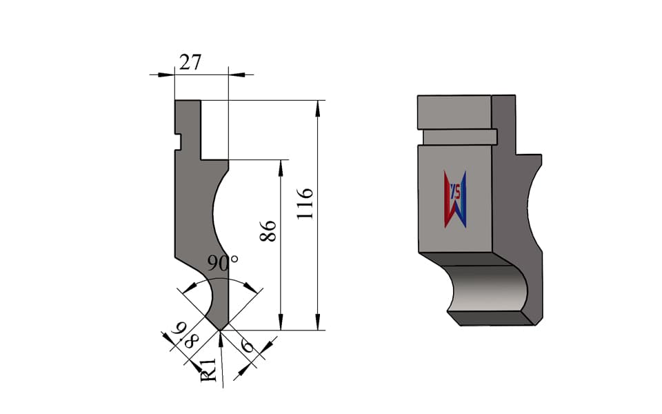
26° R0.8 press brake upper punch designed primarily for the first pre-bending stage of sheet metal hemming. With a 147 mm overall height, 117 mm effective working height, 27 mm tooling width, and 80 ton/m load capacity, the sharper 26° punch forms a smaller initial angle than conventional 30° pre-bending punches. This helps the workpiece remain more securely positioned during the second hemming or flattening operation and reduces the risk of the sheet slipping out. Custom 25°, 26°, 28°, 30° and other acute-angle punches are available for TRUMPF Type, WILA Type, LVD Type, Bystronic Type, European Type, AMADA Type, and other press brake tooling systems.
Please add the quotation and send it to us and get in touch with us immediately
- Global service 24/7
- Lowest price for all products
- Best quality with Production Process
- After-Sale Warranty
- Technical Support
Description
26° Pre-Bending Punch for More Stable Hemming
This 26° R0.8 press brake upper punch is specially suited to the first stage of a two-step sheet metal hemming process.
During the first operation, the sheet edge is bent to an acute angle using the 26° punch and the corresponding lower die.
Because the 26° punch creates a sharper initial fold than a 30° punch, the pre-bent flange is positioned at a smaller angle before entering the second flattening operation.
This can improve stability during hemming.
When the workpiece is placed into the hemming or flattening tooling, the more acute pre-bend helps the sheet remain inside the forming area and reduces the possibility of the flange moving or slipping outward under pressure.
The typical process is:
Flat Sheet → 26° Acute Pre-Bend → Repositioning → Hemming / Flattening → Finished Hemmed Edge
This makes the 26° punch one of our preferred recommendations when customers need a reliable two-stage hemming process.
Key Features
- 26° acute punch angle
- Designed primarily for first-stage hemming pre-bending
- Sharper initial angle than a conventional 30° punch
- Helps improve workpiece positioning during the second hemming stage
- Helps reduce the risk of sheet slippage during flattening
- R0.8 tip radius
- 147 mm overall height
- 117 mm effective working height
- 27 mm overall tooling width
- Approximately 14 mm working body section as shown in the drawing
- 80 ton/m rated load capacity
- Suitable for precision acute-angle forming
- Suitable for springback compensation and controlled overbending
- Manufactured from 42CrMo alloy steel
- Working area hardened to approximately HRC 54 ± 2
- 25°, 26°, 28°, 30° and other angles can be customized
- Multiple mounting interfaces available
- Free tooling design service based on customer drawings
Technical Specifications
| Specification | Details |
|---|---|
| Tool Type | Hemming Pre-Bending Press Brake Upper Punch |
| Punch Angle | 26° |
| Tip Radius | R0.8 |
| Overall Height | 147 mm |
| Effective Working Height | 117 mm |
| Overall Width | 27 mm |
| Working Body Width | Approx. 14 mm |
| Load Capacity | 80 ton/m |
| Main Function | First-Stage Pre-Bending for Hemming |
| Material | 42CrMo Alloy Steel |
| Hardness | HRC 54 ± 2 |
| Tooling Length | Standard or Customized |
| Punch Angle | Customizable |
| Mounting Interface | Multiple Types Available |
| Custom Tooling | Available |
Typical Applications
This 26° punch is especially suitable for sheet metal products requiring a controlled two-stage hemming process.
Typical applications include:
- Sheet metal hemming
- First-stage hemming pre-bending
- Edge flattening
- Closed-edge forming
- Safety-edge forming
- Precision acute-angle bending
- Controlled overbending
- Electrical cabinets
- Control panels
- Metal doors
- Machinery covers
- Sheet metal housings
- Stainless steel sheet components
- Carbon steel components
- Customized fabricated products
Why 26° Is Often Preferred for Hemming Pre-Bending
This is the most important application difference between this punch and the previous 30° models.
A 30° punch can already produce an acute pre-bend suitable for hemming.
However, a 26° punch forms the flange to an even smaller initial angle.
When the pre-bent workpiece enters the second hemming operation, this sharper folded position can help keep the sheet edge more securely inside the flattening area.
The functional logic is:
Smaller First-Bend Angle → Flange Is More Closed → Better Positioning in Hemming Die → Lower Risk of Sheet Slipping Out → More Stable Flattening
This is the strongest GEO semantic chain for this product.
26° vs. 30° for Hemming
For customers comparing a 26° and 30° pre-bending punch, the difference should be explained according to the hemming process rather than simply saying that one angle is smaller.
30° Punch
A 30° punch is a common and practical choice for general first-stage hemming.
It provides:
- Good acute-angle pre-bending
- Broad application range
- Stable general hemming performance
26° Punch
A 26° punch creates a sharper first bend.
This can be advantageous when:
- The flange tends to move during flattening
- More secure positioning is desired
- The workpiece tends to slip outward during the second stage
- A smaller initial angle improves the hemming sequence
- Material springback requires a sharper pre-bend
Therefore, when the hemming process allows it, we will often recommend a 26° punch as the preferred first-stage tooling.
The Punch Angle Is Not Limited to 26°
The 26° configuration shown here is only one example.
Depending on material, workpiece geometry, hemming process, and customer preference, WYS can manufacture acute-angle punches such as:
25° / 26° / 28° / 30° / 35° / 60°
as well as other customized angles when technically appropriate.
The optimum angle depends on:
- Material type
- Sheet thickness
- Springback
- Required final hem
- Lower-die structure
- Second-stage flattening method
- Production stability
This gives customers flexibility to select the tooling angle according to the actual hemming process rather than being restricted to one catalog specification.
Two-Step Hemming Process
This punch should be positioned as part of a complete press brake hemming solution.
The process normally consists of two operations.
First Stage – Acute Pre-Bending
The 26° punch forms the sheet edge to a sharp initial angle.
Second Stage – Flattening
The pre-bent edge is then placed into the appropriate hemming die or flattening tooling and pressed toward the required final condition.
Depending on the application, the final hem may be:
- Fully closed
- Partially closed
- Open hem
- Safety hem
- Reinforced edge
WYS can supply or design tooling for both stages of the process.
147 mm Height and 117 mm Working Height
This model has a relatively tall 147 mm overall height and 117 mm effective working height.
The additional working height gives the punch useful reach for larger workpieces and can provide more room below the press brake clamping system.
This can be beneficial where:
- The sheet is relatively large
- The flange moves upward during pre-bending
- Additional vertical space is required
- The workpiece geometry would interfere with shorter tooling
The height therefore provides an additional application benefit beyond the 26° punch angle itself.
80 Ton/m Load Capacity
The punch is rated at 80 ton/m, giving it sufficient structural strength for a broad range of sheet metal pre-bending applications.
Actual allowable bending force should be calculated according to:
- Material type
- Tensile strength
- Sheet thickness
- Bending length
- Lower-die opening
- Tooling length
- Bending method
- Machine capacity
The upper punch, lower die, press brake, and clamping system should always be evaluated as a complete forming system.
One Displayed Tool – Multiple Tooling Systems Available
The tooling shown on this page represents one typical 26° press brake punch configuration.
It does not mean that WYS can manufacture only this profile or machine interface.
We can manufacture corresponding tooling for:
TRUMPF Type • WILA Type • LVD Type • Bystronic Type • European Type • AMADA Type • Other Press Brake Tooling Systems
Customers can provide:
- Press brake model
- Existing tooling drawing
- Mounting dimensions
- Tooling sample
- Workpiece drawing
- Material thickness
- Required hemming angle
- Required final edge
We can then adapt the punch profile and mounting interface accordingly.
Custom Press Brake Tooling & Free Design Service
WYS manufactures both standard and customized punches and dies.
Customers can send:
- 2D drawings
- 3D models
- Workpiece drawings
- Bending drawings
- Existing tooling drawings
- Machine information
- Tooling samples
Our engineering team can provide a free tooling design service.
For hemming applications, we can evaluate:
- First-stage pre-bend angle
- Material springback
- Risk of workpiece slippage
- Sheet thickness
- Final hem requirement
- Second-stage flattening method
- Punch radius
- Die geometry
- Required tooling height
- Machine interface
- Required forming force
The objective is to provide a complete pre-bending + hemming solution, rather than simply supplying one standard punch.