60° R0.8 Double-Side Clearance Press Brake Upper Punch – 145 mm Height, 115 mm Working Height, 10 mm Tip, 70 Ton/m
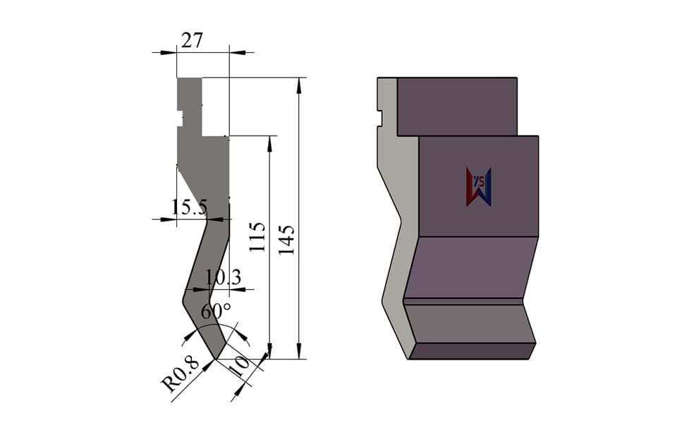
Special-profile 60° R0.8 press brake upper punch featuring clearance geometry on both the front and rear sides of the tool. With a 145 mm overall height, 115 mm effective working height, 10 mm tip width, and 70 ton/m load capacity, this double-side clearance design helps reduce interference between the punch and previously formed sections of complex workpieces. Custom configurations are available for TRUMPF Type, WILA Type, LVD Type, Bystronic Type, AMADA Type, and other press brake tooling systems.
Please add the quotation and send it to us and get in touch with us immediately
- Global service 24/7
- Lowest price for all products
- Best quality with Production Process
- After-Sale Warranty
- Technical Support
Description
Special 60° Punch with Front and Rear Workpiece Clearance
This 60° R0.8 double-side clearance press brake punch features a distinctive offset profile designed to provide additional workpiece clearance on both sides of the upper tool.
Unlike a conventional straight punch, the body profile is relieved in both the front and rear directions. This creates additional space around the tooling during the bending process and can help prevent previously formed flanges, side walls, or other sections of the workpiece from contacting the punch body.
This structure is particularly advantageous when bending complex, asymmetric, multi-bend, or specially shaped sheet metal components where a conventional straight punch may cause interference.
The punch has a 145 mm overall height and 115 mm effective working height, providing sufficient reach for complex forming operations. Its R0.8 tip radius and 10 mm tip width provide a stable working geometry, while the 70 ton/m rated load capacity makes the tool suitable for a wide range of industrial sheet metal bending applications.
Key Features
- 60° acute-angle punch geometry
- Special profile with front-side and rear-side clearance
- Designed to reduce tool-to-workpiece interference
- Suitable for complex and specially shaped sheet metal components
- 145 mm overall height
- 115 mm effective working height
- 27 mm overall tooling width
- Special body profile with approximately 15.5 mm and 10.3 mm local sections as shown in the drawing
- 10 mm tip width
- R0.8 tip radius
- 70 ton/m rated load capacity
- Suitable for multi-step and restricted-clearance bending
- Manufactured from 42CrMo alloy steel
- Working area heat treated to approximately HRC 54 ± 2
- Multiple mounting systems available
- Profile and dimensions can be fully customized
- Free tooling design support available from customer workpiece drawings
Technical Specifications
| Specification | Details |
|---|---|
| Tool Type | Double-Side Clearance Press Brake Upper Punch |
| Punch Angle | 60° |
| Tip Radius | R0.8 |
| Overall Height | 145 mm |
| Effective Working Height | 115 mm |
| Overall Width | 27 mm |
| Tip Width | 10 mm |
| Load Capacity | 70 ton/m |
| Clearance Structure | Front & Rear Clearance |
| Material | 42CrMo Alloy Steel |
| Hardness | HRC 54 ± 2 |
| Primary Application | Complex / Restricted-Clearance Bending |
| Tooling Length | Standard or Customized |
| Mounting Interface | Multiple Types Available |
| Custom Tooling | Available |
Typical Applications
This special 60° punch is especially suitable for sheet metal parts where workpiece geometry creates interference around both sides of the upper tool.
Typical applications include:
- Complex sheet metal bending
- Special-profile workpieces
- Multi-step bending
- Previously formed components
- Return flange bending
- Box and enclosure components
- Offset profiles
- Components with protruding flanges
- Restricted-clearance bending
- Asymmetric workpieces
- Deep or irregular profiles
- Electrical cabinets and enclosures
- Machinery covers
- Industrial equipment panels
- Customized fabricated components
Double-Side Clearance for Complex Workpieces
The most important feature of this punch is not simply its 60° angle.
Its real advantage is the special relieved body geometry on both the front and rear sides.
During complex bending operations, the workpiece often already contains one or more formed sections. These existing flanges or walls may move toward the punch body during the next bending step.
With a conventional straight punch, this can cause:
- Workpiece-to-tool collision
- Restricted bending movement
- Difficulty positioning the workpiece
- Limited bending sequence options
- Surface marking or deformation
- Inability to complete the intended bend
The special profile of this punch provides additional clearance on both sides, helping the formed portions of the workpiece pass around the punch body with less interference.
Its functional logic can be summarized as:
Special Punch Profile → Front & Rear Clearance → Reduced Interference → More Flexible Bending Sequence → Complex Workpiece Bending
This is the semantic chain I recommend emphasizing throughout the page.
More Than a Conventional 60° Acute-Angle Punch
A conventional 60° punch is mainly selected because of its acute tooling angle.
This model adds another important function:
workpiece clearance.
That means the tool can satisfy two different requirements at the same time:
60° geometry for acute-angle forming
and
special body relief for interference avoidance
This combination makes it particularly useful for customers whose bending difficulty is caused not only by the required angle, but also by the shape of the workpiece itself.
Designed Around the Workpiece, Not Limited to One Standard Profile
This section is especially important for this product because its unusual shape naturally demonstrates your customized-tooling capability.
The tooling shown on this page is one representative special-profile punch manufactured by WYS. It does not mean that we are limited to this exact shape, dimension, or mounting interface.
The appropriate clearance profile depends on the customer's actual component.
For different applications, we can customize:
- Front-side clearance
- Rear-side clearance
- Clearance depth
- Clearance angle
- Punch body thickness
- Overall height
- Effective working height
- Punch angle
- Tip width
- Tip radius
- Tooling length
- Segmentation
- Mounting interface
- Special interference-relief geometry
Customers can send us a workpiece drawing or 3D model, and our engineering team can evaluate where interference is likely to occur during the bending sequence.
Based on this information, we can design a suitable punch profile to provide the required workpiece clearance.
Multiple Press Brake Tooling Systems Available
The drawing shown here represents only one tooling interface.
WYS can manufacture corresponding special-profile punches for different press brake tooling systems, including:
TRUMPF Type • WILA Type • LVD Type • Bystronic Type • AMADA Type • European Type • Other Tooling Systems
Customers do not need to find a standard catalog tool with exactly the same shape.
They can provide:
- Machine model
- Existing punch drawing
- Clamping dimensions
- Tooling sample
- Workpiece drawing
- Bending sequence
- Required bend dimensions
We can then adapt the special punch geometry to the required press brake interface.
This reinforces an important message for both customers and search engines:
WYS manufactures the required bending geometry for the customer's application, rather than being limited to one standard tooling catalog.
Product Details & Manufacturing Quality
This special-profile upper punch is manufactured from 42CrMo alloy steel, selected for its strength, toughness, wear resistance, and suitability for precision press brake tooling.
The working area is heat treated to approximately HRC 54 ± 2, helping maintain the punch profile and tip geometry during repeated bending operations.
The R0.8 tip radius provides a relatively compact working radius, while the 10 mm tip width gives the working section sufficient structural support for the rated load.
The tooling is rated at 70 ton/m.
Because the punch contains special relieved sections, actual permissible bending force must always be evaluated according to the specific tooling geometry, tooling length, sheet material, thickness, V-die opening, and bending method.
For customized versions, our engineering team can review these factors before production.
Standard & Custom Press Brake Tooling
WYS supplies both standard press brake tooling and custom-designed punches and dies for complex sheet metal parts.
For special applications, customers can send:
- 2D workpiece drawings
- 3D models
- Bending drawings
- Existing tooling drawings
- Press brake information
- Workpiece samples
We provide a free tooling design service to help determine an appropriate bending solution.
For this type of special-clearance punch, our engineers can evaluate:
- Existing flange positions
- Workpiece movement during bending
- Front-side interference
- Rear-side interference
- Required bending sequence
- Punch-to-workpiece clearance
- Required bend angle
- Material springback
- Bending force
- Press brake mounting interface
This allows the tooling to be designed according to the actual workpiece geometry and bending process, rather than simply selecting the nearest standard punch.