JFY Type D Station RO15.1 Thin Turret Round Embossing Tool
The JFY Type D Station RO15.1 Thin Turret Round Embossing Tool is designed to form a nominal Ø15.1 mm circular emboss in 2 mm sheet metal on compatible thin turret punch presses. Supplied as a matching upper and lower forming-tool set, it creates a controlled raised or recessed feature through cold forming rather than cutting and removing material. Emboss diameter, forming height, direction, corner radius, material compatibility and tooling configuration can be customized according to the customer’s finished-part drawing.
Please add the quotation and send it to us and get in touch with us immediately
- Global service 24/7
- Lowest price for all products
- Best quality with Production Process
- After-Sale Warranty
- Technical Support
Description
The JFY Type D Station RO15.1 Thin Turret Round Embossing Tool is a specialized sheet metal forming tool developed for creating a nominal Ø15.1 mm circular emboss in 2 mm thick sheet material.
Unlike conventional punching tools that cut and remove a slug, this embossing tool plastically deforms the sheet between a matching male and female forming section. The material is displaced into the designed cavity to create a raised or recessed circular feature while remaining part of the workpiece.
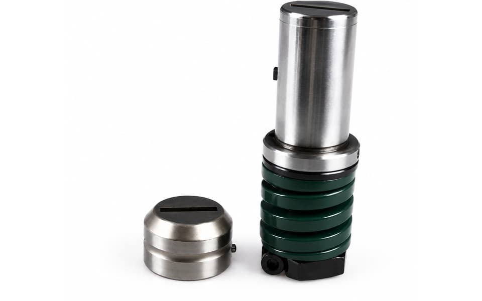
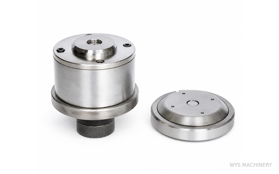
The tooling shown consists of a complete upper and lower forming-tool combination. During the machine stroke, the male forming section progressively pushes the sheet into the corresponding female cavity. Correct coordination between the two components controls the emboss diameter, forming height, wall transition and surrounding sheet flatness.
“RO15.1” identifies the nominal round emboss profile with a diameter of 15.1 mm. It should not automatically be interpreted as the size of every internal tooling component. The male and female forming dimensions must include the appropriate forming gap, corner radii and material allowance for the specified 2 mm sheet.
This product uses a D Station thin turret configuration, providing the installation space and structural support required for the forming assembly. Compatibility must still be checked using the exact punch press model, existing tooling dimensions and station structure.
The standard application described here is designed around 2 mm sheet thickness. If the material type, thickness or mechanical properties change, the forming clearance and profile may also need to be redesigned. A tool manufactured for one application should not automatically be used on a substantially different material or thickness without engineering confirmation.
WYS Machinery can customize the emboss diameter, forming height, forming direction, transition radius, relief, tool material and installation structure according to the customer’s machine and finished-part drawing. Free tooling design support is available for custom sheet metal components.
This tooling is manufactured by WYS Machinery as compatible replacement tooling. References to JFY describe the applicable tooling configuration and do not imply original manufacture, authorization or official affiliation.
Key Features
- JFY Type thin turret forming tooling
- D Station tooling configuration
- RO15.1 circular emboss profile
- Nominal emboss diameter of Ø15.1 mm
- Standard design for 2 mm sheet thickness
- Complete matching upper and lower forming-tool set
- Forms the sheet without cutting a conventional slug
- Suitable for raised or recessed round features
- Controlled male-and-female forming geometry
- Precision-machined forming surfaces
- Customized forming clearance
- Smooth transition radii to reduce material concentration
- Tool material and heat treatment selected by application
- Replaceable components available according to design
- Custom emboss diameter and height available
- Custom forming direction available
- Designed from finished-part drawings or samples
- Free tooling design and application support
Technical Specifications
| Specification | Details |
|---|---|
| Product Category | Thin Turret Forming Tooling |
| Tool Type | Round Embossing Tool / Dimple Forming Tool |
| Compatibility Type | JFY Type |
| Station | D Station |
| Shape Designation | RO15.1 |
| Emboss Shape | Round |
| Nominal Emboss Diameter | Ø15.1 mm |
| Standard Sheet Thickness | 2 mm |
| Forming Method | Cold Sheet Metal Forming |
| Supply Configuration | Matching Upper and Lower Tool Set |
| Material Removal | No Conventional Slug Removal |
| Forming Direction | Customized According to Part Drawing |
| Emboss Height | Customized According to Requirements |
| Forming Clearance | Designed for Material and Thickness |
| Transition Radius | Customized |
| Tool Material | Selected According to Application |
| Heat Treatment | Selected According to Tool Material and Forming Conditions |
| Applicable Material | Confirmed According to Customer Application |
| Customization | Diameter, Height, Direction, Radius, Clearance and Tool Structure |
How the Embossing Tool Works
The RO15.1 embossing tool creates a three-dimensional circular feature through controlled plastic deformation.
The forming process generally includes:
- The sheet is positioned between the upper and lower forming components
- The punch press initiates a controlled forming stroke
- The male section pushes the sheet toward the female cavity
- Material flows around the designed transition radius
- The matching profile controls the emboss diameter and height
- The tool retracts and releases the formed component
Because the process forms rather than cuts the material, the tool normally does not create the conventional round slug produced by a piercing punch.
The final shape depends on the tooling geometry, sheet material, thickness, machine stroke and material springback.
RO15.1 Emboss Dimensions
RO15.1 represents the nominal Ø15.1 mm emboss profile specified for the finished sheet metal component.
A complete emboss specification should include more than diameter. Important dimensions include:
- Emboss outside diameter
- Emboss height or depth
- Top diameter, if applicable
- Transition radius
- Side-wall angle
- Forming direction
- Sheet thickness
- Distance from the emboss to nearby holes or edges
Since only the Ø15.1 mm diameter and 2 mm sheet thickness are currently specified, the emboss height and detailed profile should be confirmed from the customer’s drawing before manufacturing.
Suitable for 2 mm Sheet Thickness
This tooling configuration is designed for a nominal sheet thickness of 2 mm.
The actual tool geometry must consider:
- Sheet material
- Actual thickness tolerance
- Tensile strength
- Yield strength
- Elongation
- Surface condition
- Rolling direction
- Required emboss height
- Required surface quality
A 2 mm mild-steel sheet and a 2 mm stainless-steel sheet do not necessarily require exactly the same forming geometry or machine settings. Material information should therefore be provided when ordering.
Raised and Recessed Embossing
Depending on the installation direction and finished-part requirements, a round emboss may appear as:
- A raised feature on the upper surface
- A raised feature on the lower surface
- A recessed circular feature
- A support dimple
- A locating or spacing feature
The customer should identify the viewing side of the component and clearly mark the emboss direction on the drawing.
If upward and downward embosses are both required, separate tooling configurations or an appropriate reversible design may be needed depending on the machine and tooling structure.
Emboss Height and Forming Limits
The emboss height must be selected according to the diameter, sheet thickness and formability of the material.
Excessive forming height may cause:
- Material thinning
- Surface cracking
- Distortion around the emboss
- Tearing at the transition radius
- Excessive forming force
- Tool interference
- Difficulty releasing the workpiece
A suitable transition radius and controlled forming depth help distribute strain more evenly.
WYS Machinery can evaluate the proposed emboss height after receiving the finished-part drawing and material information.
Forming Clearance
Embossing-tool clearance is different from the cutting clearance used for ordinary punch-and-die sets.
For a cutting tool, clearance is selected to control fracture and slug separation. For an embossing tool, the gap between the male and female profiles must allow the 2 mm sheet to flow and form without being excessively squeezed or trapped.
Forming-clearance design considers:
- Sheet thickness
- Material type
- Material strength
- Material elongation
- Emboss diameter
- Required forming height
- Transition radius
- Surface-quality requirements
- Material springback
- Tool release requirements
Incorrect forming clearance can cause excessive thinning, scratches, cracking, uncontrolled dimensions or difficulty separating the sheet from the tool.
Forming Force and Machine Settings
Required forming force depends on:
- Sheet material
- Sheet thickness
- Emboss diameter
- Forming height
- Transition radius
- Tool geometry
- Material strength
- Machine stroke
- Forming speed
Even though this is a D Station tool, physical installation capacity does not by itself confirm that the forming operation is suitable. Available machine tonnage, stroke control and shut-height settings must also be checked.
The tool should be commissioned using a controlled trial stroke. The forming depth should be increased gradually until the required emboss height is achieved.
Typical Applications
The RO15.1 D Station embossing tool can be used in:
- Electrical cabinets and control enclosures
- Switchgear panels
- Electronic equipment housings
- Sheet metal mounting plates
- Machinery guards
- Automotive sheet metal components
- HVAC components
- Metal furniture
- Stainless steel equipment
- Industrial control panels
- Brackets and support plates
- General precision sheet metal fabrication
Typical emboss functions include:
- Increasing local panel stiffness
- Creating spacer or support points
- Providing locating features
- Improving component positioning
- Creating screw or assembly seats
- Producing clearance around components
- Creating decorative circular features
- Improving sheet metal structure without adding separate parts
Structural and Functional Advantages
A properly designed emboss can provide additional functionality without welding or installing a separate component.
Potential benefits include:
- Increased local rigidity
- Improved sheet positioning
- Reduced need for separate spacers
- Repeatable assembly location
- Fewer secondary operations
- Improved component clearance
- Integrated functional features
- Consistent production on CNC punch presses
The actual structural benefit depends on the emboss dimensions, sheet material and surrounding component design.
Surface Quality and Part Flatness
Embossing causes local material displacement and may influence the flatness of the surrounding sheet.
To improve forming quality, the tool design should consider:
- Smooth forming surfaces
- Appropriate transition radii
- Correct forming clearance
- Controlled stroke depth
- Adequate distance from sheet edges
- Adequate distance from nearby holes
- Material rolling direction
- Workpiece support
- Tool lubrication, where appropriate
If the emboss is positioned too close to an edge, bend line or existing opening, surrounding distortion may increase.
Manufacturing Quality
The embossing tool is manufactured using controlled machining, heat treatment, precision grinding and assembly processes.
Quality inspection can include:
- Male forming-profile measurement
- Female cavity measurement
- Emboss-diameter verification
- Forming-clearance inspection
- Transition-radius inspection
- Tool concentricity checking
- D Station dimensional inspection
- Tool-height inspection
- Forming-direction confirmation
- Surface-finish inspection
- Assembly and movement testing
- Trial forming where required
Accurate matching of the upper and lower profiles helps control the emboss dimensions and reduce uneven forming loads.
Installation and Trial Forming
Before installation:
- Confirm the exact punch press model
- Verify the D Station tooling structure
- Confirm the RO15.1 profile
- Check the sheet material and 2 mm thickness
- Confirm the required emboss direction
- Confirm the target emboss height
- Inspect the upper and lower forming surfaces
- Clean the tooling and station
- Confirm tool alignment
- Check machine stroke and shut height
During trial forming:
- Start with a conservative forming depth
- Use a test sheet matching the production material
- Increase forming depth gradually
- Measure the emboss diameter and height
- Inspect for cracking and thinning
- Check surrounding sheet flatness
- Confirm that the workpiece releases smoothly
- Save the verified CNC and machine settings
The tool should not be tested initially at maximum forming depth without confirming the setup.
Maintenance
Regular maintenance should include:
- Cleaning the male and female forming profiles
- Removing metal particles and material residue
- Inspecting the transition radii
- Checking for surface scratches or galling
- Inspecting tool alignment
- Checking moving or spring-loaded components
- Applying suitable lubrication where required
- Inspecting screws and retaining components
- Protecting the forming surfaces during storage
Unlike cutting tools, embossing tools are not normally maintained only by sharpening a cutting edge. Wear, surface damage and dimensional change of the complete forming profile must be evaluated.
Ordering Information Required
| Required Information | Purpose |
|---|---|
| Punch Press Manufacturer and Model | Confirms machine compatibility |
| Tooling System | Confirms the thin turret structure |
| Station | Confirms D Station dimensions |
| Finished-Part Drawing | Defines the complete emboss profile |
| Emboss Diameter | Confirms RO15.1 or another custom diameter |
| Emboss Height or Depth | Defines the forming stroke and profile |
| Forming Direction | Confirms raised or recessed orientation |
| Sheet Material | Supports geometry and material selection |
| Sheet Thickness | Confirms the standard 2 mm application |
| Material Strength | Supports forming-force evaluation |
| Nearby Holes and Edges | Supports distortion and clearance evaluation |
| Existing Tooling Sample | Supports compatible replacement production |
| Required Quantity | Confirms production scope |
Standard and Custom Thin Turret Forming Tooling
WYS Machinery supplies standard and custom thin turret forming tools for a wide range of sheet metal applications.
Available forming-tool options include:
- Round embossing tools
- Dimple forming tools
- Extrusion forming tools
- Knockout tools
- Countersink tools
- Louver tools
- Bridge forming tools
- Lance-and-form tools
- Rib forming tools
- Marking tools
- Custom special forming tools
Customization options include:
- Emboss diameter
- Emboss height or depth
- Raised or recessed direction
- Transition radius
- Forming angle
- Forming clearance
- Sheet material and thickness
- Tool material
- Heat treatment
- Surface treatment
- Machine interface
- Station configuration
Customers can send their finished-part drawing, machine model, sheet material and thickness. Our engineering team can design a suitable forming-tool structure and provide free tooling design support.
Product Identification and Frequently Asked Questions
What does RO15.1 mean?
RO15.1 identifies a nominal round emboss profile with a diameter of 15.1 mm.
Is this a round-hole punching tool?
No. It is an embossing or dimple-forming tool. It deforms the sheet to create a three-dimensional circular feature rather than cutting out a conventional round hole.
Is the product suitable for 2 mm sheet?
Yes. The specified standard configuration is designed for 2 mm sheet. The exact sheet material should still be confirmed before manufacturing.
Does the tool include both upper and lower components?
Yes. The pictured product is a matching forming-tool assembly consisting of upper and lower components.
Can the emboss height be customized?
Yes. The emboss height or depth can be designed according to the finished-part drawing and material-forming limits.
Can the diameter be changed from Ø15.1 mm?
Yes. Other diameters can be manufactured according to customer requirements.
Can it form both upward and downward embosses?
The forming direction can be customized. The required viewing side and emboss direction should be marked clearly on the drawing.
Can the tooling be used for material thicker or thinner than 2 mm?
A customized version can be designed for other thicknesses. The forming clearance and profile should be redesigned rather than assuming the 2 mm tool is universally suitable.
Is this original JFY tooling?
No. It is compatible replacement tooling manufactured by WYS Machinery. The JFY reference describes compatibility and does not imply original manufacture or official affiliation.