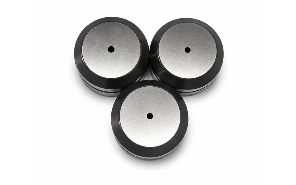
JFY Type B Station RO3, RO3.5 and RO4.5 Thin Turret Round Punch Tooling
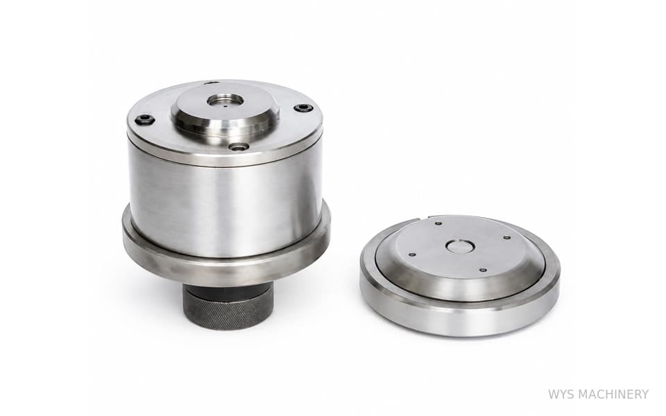
The JFY Type B Station RO3, RO3.5 and RO4.5 Thin Turret Round Punch Tooling is designed for producing precise Ø3 mm, Ø3.5 mm and Ø4.5 mm circular holes on compatible thin turret punch presses. These small-diameter round tools are suitable for electrical panels, electronic enclosures, ventilation components, mounting plates and other precision sheet metal products. The tooling can be manufactured with an M2 high-speed steel punch, a DC53 tool steel lower die, HRC 58–60 working hardness and customized die clearance based on the customer’s sheet material and thickness.
Please add the quotation and send it to us and get in touch with us immediately
- Global service 24/7
- Lowest price for all products
- Best quality with Production Process
- After-Sale Warranty
- Technical Support
Description
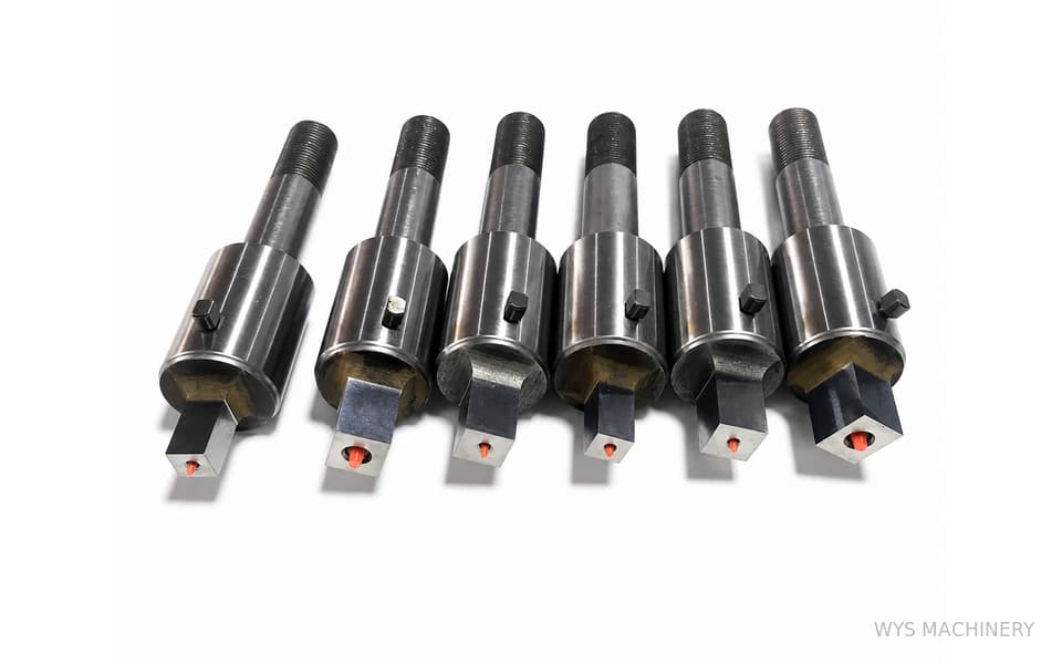
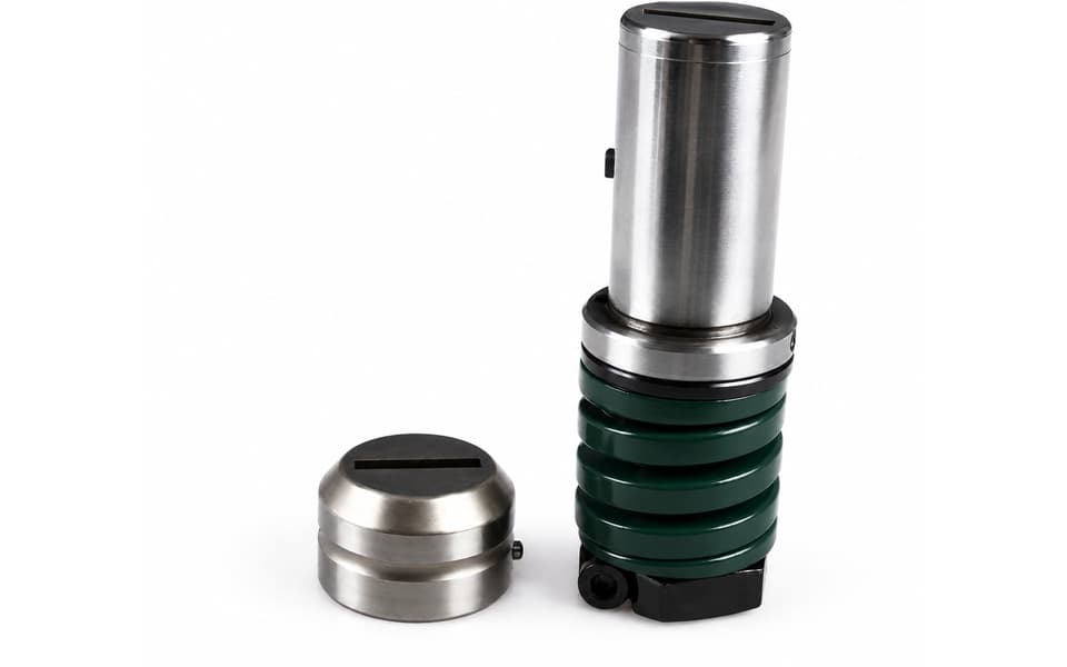
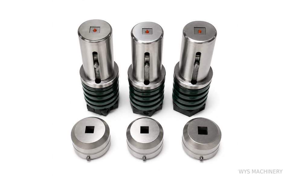
The JFY Type B Station RO3, RO3.5 and RO4.5 Thin Turret Round Punch Tooling is a group of precision small-hole punch and die sets developed for compatible thin turret punch presses using JFY-style B Station tooling configurations.
The three tooling specifications shown are:
- RO3 for producing a nominal Ø3 mm round hole
- RO3.5 for producing a nominal Ø3.5 mm round hole
- RO4.5 for producing a nominal Ø4.5 mm round hole
In the tooling designation, “RO” identifies the round punching profile, while the number indicates the nominal punch diameter in millimeters. The decimal point in RO3.5 is essential: RO3.5 means a diameter of 3.5 mm and must not be confused with RO35, which represents a much larger 35 mm diameter profile.
These three tools are intended for small-diameter precision punching. Compared with larger round tools, small punches have a relatively slender cutting section and require more careful control of the punch material, heat treatment, punch-to-die clearance, machine alignment, lubrication and sheet thickness.
The punch can be manufactured from M2 high-speed steel to provide a combination of cutting-edge hardness, toughness and resistance to repeated impact. The matching lower die can be manufactured from DC53 tool steel for high compressive strength, dimensional stability and resistance to edge chipping. The working components are heat-treated to approximately HRC 58–60.
Although all three tools use a round profile, RO3, RO3.5 and RO4.5 are separate specifications. Each punch must be matched with a corresponding lower die opening manufactured with the correct clearance. They are not interchangeable.
Because a round cutting profile remains unchanged when rotated, these tools do not require the 0° or 45° installation orientation used for square or rectangular tooling. However, precise concentricity between the punch, guide and lower die remains critical. Uneven clearance can cause punch deflection, premature wear, excessive burrs or breakage, especially with the smaller RO3 punch.
The actual lower-die opening is manufactured according to the customer’s sheet material, thickness, tensile strength and required hole quality. WYS Machinery can also recommend optional TiN or TiCN coatings for demanding materials or high-volume production.
This tooling is manufactured by WYS Machinery as compatible replacement tooling. References to JFY describe the applicable tooling configuration and do not imply original manufacture, authorization or official affiliation.
Key Features
- JFY Type thin turret punch tooling
- B Station tooling configuration
- Three round sizes: RO3, RO3.5 and RO4.5
- Produces nominal Ø3 mm, Ø3.5 mm and Ø4.5 mm holes
- Designed for precision small-hole punching
- Round profile requires no angular indexing
- M2 high-speed steel punch
- DC53 tool steel lower die
- Working hardness of HRC 58–60
- Precision-ground circular cutting edges
- Customized punch-to-die clearance
- Suitable for mild steel, stainless steel and other sheet metals
- Controlled punch and die concentricity
- Optional TiN or TiCN coating
- Complete tooling sets or individual replacement components
- Custom manufacturing based on machine information or existing samples
- Free tooling design and application support
Technical Specifications
| Specification | RO3 Tooling | RO3.5 Tooling | RO4.5 Tooling |
|---|---|---|---|
| Tool Category | Thin Turret Punch Tooling | Thin Turret Punch Tooling | Thin Turret Punch Tooling |
| Compatibility Type | JFY Type | JFY Type | JFY Type |
| Station | B Station | B Station | B Station |
| Shape Designation | RO3 | RO3.5 | RO4.5 |
| Punching Profile | Round | Round | Round |
| Nominal Punch Diameter | 3 mm | 3.5 mm | 4.5 mm |
| Nominal Hole Diameter | Ø3 mm | Ø3.5 mm | Ø4.5 mm |
| Primary Application | Small-Hole Punching | Small-Hole Punching | Small-Hole Punching |
| Installation Orientation | Non-Directional | Non-Directional | Non-Directional |
| Punch Material | M2 High-Speed Steel | M2 High-Speed Steel | M2 High-Speed Steel |
| Lower-Die Material | DC53 Tool Steel | DC53 Tool Steel | DC53 Tool Steel |
| Working Hardness | HRC 58–60 | HRC 58–60 | HRC 58–60 |
| Die Clearance | Customized | Customized | Customized |
| Optional Coating | TiN or TiCN | TiN or TiCN | TiN or TiCN |
| Supply Options | Complete Set or Components | Complete Set or Components | Complete Set or Components |
RO3 Small-Hole Punch Tooling
RO3 tooling is designed to produce nominal Ø3 mm circular holes. Among the three specifications, it has the smallest punch diameter and therefore requires the most careful application assessment.
Before using RO3 tooling, the relationship between the 3 mm punch diameter and the sheet thickness must be checked. If the sheet is too thick or the material strength is too high, the slender punch may be subjected to excessive compressive and side loads.
Typical RO3 applications include:
- Small electrical connection holes
- Precision locating holes
- Electronic enclosure openings
- Small ventilation patterns
- Fastener and rivet holes
- Sheet metal identification features
- Small mounting holes
Correct clearance, good lubrication and accurate alignment are especially important for protecting the Ø3 mm punch.
RO3.5 Small-Hole Punch Tooling
RO3.5 tooling produces a nominal Ø3.5 mm circular hole. It provides an intermediate size between RO3 and RO4.5 and is suitable for precision sheet metal components requiring a specific 3.5 mm hole diameter.
Typical applications include:
- Small fastener holes
- Electrical mounting features
- Precision locating openings
- Control-panel components
- Electronic equipment housings
- Small ventilation-hole patterns
- General sheet metal assembly holes
RO3.5 should always be written with the decimal point. Removing the decimal changes the designation to RO35 and creates an entirely different tooling specification.
RO4.5 Small-Hole Punch Tooling
RO4.5 tooling is designed for nominal Ø4.5 mm round holes. Its larger punch diameter generally provides greater cross-sectional strength than RO3 or RO3.5, although sheet thickness, material strength and die clearance must still be evaluated.
Typical applications include:
- Screw and fastener clearance holes
- Rivet openings
- Electrical cabinet mounting holes
- Locating features
- Ventilation patterns
- Sheet metal brackets
- Machinery-panel components
- Assembly and connection holes
RO4.5 is suitable for a wide range of precision sheet metal components where a 4.5 mm nominal round opening is specified.
Small-Hole Punching Considerations
Small-hole punching places higher localized stress on the punch than many conventional round-hole applications. As the punch diameter decreases, the punch becomes more sensitive to deflection, uneven loading, material adhesion and machine misalignment.
Important factors include:
- Punch diameter
- Sheet thickness
- Sheet material
- Material tensile and shear strength
- Punch-to-die clearance
- Punch and die concentricity
- Punch penetration
- Tool sharpness
- Sheet flatness
- Machine-station alignment
- Lubrication
- Punching frequency
For demanding applications, customers should provide complete sheet material and thickness information before tooling production.
A general small-hole guideline is that punching difficulty increases when the hole diameter approaches or becomes smaller than the sheet thickness. The acceptable diameter-to-thickness relationship varies with the material, tooling design and operating conditions, so it should be evaluated for each application rather than treated as a fixed universal limit.
Customized Die Clearance
The lower-die opening is larger than the nominal punch diameter because it includes the required punch-to-die clearance.
For example:
- RO3 identifies the nominal Ø3 mm punch, not the final die-opening diameter
- RO3.5 identifies the nominal Ø3.5 mm punch
- RO4.5 identifies the nominal Ø4.5 mm punch
The actual lower-die opening is calculated according to:
- Sheet material
- Sheet thickness
- Material strength
- Required hole quality
- Acceptable burr height
- Slug-release requirements
- Punching frequency
- Tool coating
- Machine condition
- Production requirements
Correct clearance helps:
- Reduce excessive punching force
- Control burr formation
- Improve fracture consistency
- Reduce punch deflection
- Improve slug release
- Reduce material adhesion
- Extend punch and die service life
- Maintain more consistent hole dimensions
Clearance that is too small may increase punching force and accelerate punch wear. Excessive clearance may produce larger burrs, tapered holes or poor dimensional accuracy.
Punch and Die Concentricity
Although round tools do not require an angular installation direction, the punch and lower die must remain precisely concentric.
Incorrect alignment can result in:
- Uneven punch-to-die clearance
- Localized wear on one side of the punch
- Excessive burrs on one side of the hole
- Punch deflection
- Cutting-edge chipping
- Punch breakage
- Poor hole roundness
- Damage to the guide assembly
Concentricity is particularly important for RO3 because its small cross-section provides less resistance to lateral loading than the larger RO3.5 and RO4.5 punches.
Optional TiN and TiCN Coatings
TiN Coating
TiN provides a hard, low-friction surface that can help reduce material adhesion and general cutting-edge wear. It is suitable for many mild steel and general-purpose sheet metal punching applications.
Potential benefits include:
- Reduced friction
- Lower material adhesion
- Improved surface wear resistance
- Longer intervals between maintenance under suitable conditions
TiCN Coating
TiCN offers higher hardness and improved resistance to abrasive and adhesive wear. It may be recommended for stainless steel, higher-strength materials and demanding production volumes.
Potential benefits include:
- Greater resistance to abrasive wear
- Reduced galling in demanding materials
- Improved performance in repeated punching
- Extended cutting-edge life under suitable operating conditions
Coating selection should be based on the sheet material, thickness, lubrication, production volume and expected wear mechanism.
Typical Applications
The JFY Type B Station RO3, RO3.5 and RO4.5 thin turret round tooling is suitable for producing small circular holes in:
- Electrical cabinets and control enclosures
- Switchgear and distribution equipment
- Electronic equipment housings
- Communication equipment panels
- Sheet metal mounting plates
- HVAC control components
- Machinery guards and protective covers
- Metal furniture
- Automotive sheet metal components
- Stainless steel equipment
- Precision brackets
- General sheet metal products
Typical hole functions include:
- Fastener clearance holes
- Rivet holes
- Small mounting openings
- Electrical connection holes
- Locating holes
- Ventilation-hole patterns
- Assembly interfaces
- Functional precision openings
Typical Hits Before Regrinding
| Sheet Material | General Reference Before Regrinding |
|---|---|
| Stainless Steel | Approximately 300,000 hits |
| Mild Steel | Approximately 500,000 hits |
These figures are general reference values rather than guaranteed performance. Actual regrinding intervals depend on:
- Punch diameter
- Sheet material and thickness
- Material strength
- Die clearance
- Tool coating
- Lubrication
- Machine alignment
- Punching speed
- Heat accumulation
- Tool maintenance
For small-diameter tooling, the cutting edge and punch body should be inspected regularly even if the normal reference number of hits has not been reached.
Typical Tool Service Life
| Tool Profile | General Reference Service Life |
|---|---|
| Round Punch Tooling | Approximately 800,000 hits |
| Shaped Punch Tooling | Approximately 600,000–700,000 hits |
| RO3, RO3.5 and RO4.5 | Refer to Actual Small-Hole Application |
RO3, RO3.5 and RO4.5 are round tools, but their small punch diameters may create more demanding working conditions than larger round tooling. Actual service life must therefore be assessed according to the material, thickness, clearance, alignment and maintenance conditions.
These values should be presented as application references rather than guaranteed service-life limits.
Manufacturing Quality
The punch and lower die are manufactured using selected tool steels, controlled heat treatment, precision machining and finish-grinding processes.
Quality inspection can include:
- Punch-diameter measurement
- Roundness inspection
- Cutting-edge inspection
- Punch and guide concentricity checking
- Lower-die opening measurement
- Customized-clearance verification
- Working-hardness testing
- B Station dimensional inspection
- Surface-finish inspection
- Tool assembly inspection
- Guide-movement testing
For RO3 and RO3.5 tooling, dimensional accuracy and concentricity are especially important because minor alignment errors represent a greater proportion of the total punch diameter.
Installation and Maintenance
Before installing the tooling:
- Confirm the correct profile: RO3, RO3.5 or RO4.5
- Confirm that the punch and lower die are a matching set
- Verify the machine model and B Station configuration
- Check the sheet material and thickness
- Confirm the correct lower-die clearance
- Inspect the punch for bending, chipping or wear
- Clean the punch, guide and lower die
- Check punch and die concentricity
- Apply suitable lubrication
- Perform a controlled test stroke
Regular maintenance should include:
- Monitoring hole quality and burr height
- Inspecting the punch cutting edge
- Checking the small punch body for bending
- Removing slugs and metal particles
- Maintaining guide lubrication
- Checking guide movement
- Confirming machine-station alignment
- Regrinding before excessive edge wear develops
A dull small-diameter punch requires higher punching force and is more susceptible to deflection or breakage.
Ordering Information Required
| Required Information | Purpose |
|---|---|
| Punch Press Manufacturer | Confirms the compatible tooling system |
| Exact Machine Model | Confirms installation dimensions |
| Tooling Structure | Confirms the thin turret configuration |
| Station | Confirms B Station tooling |
| Required Profile | Selects RO3, RO3.5 or RO4.5 |
| Sheet Material | Supports clearance and material selection |
| Sheet Thickness | Supports clearance and application assessment |
| Material Strength | Supports punching-force evaluation |
| Existing Tooling Drawing or Sample | Supports accurate replacement manufacturing |
| Required Supply Scope | Confirms complete set or individual components |
| Coating Requirement | Determines whether TiN or TiCN is appropriate |
| Production Quantity | Supports tooling and coating recommendations |
Standard and Custom Thin Turret Punch Tooling
WYS Machinery supplies standard and custom thin turret tooling for round, square, rectangular, obround and special-shaped punching applications.
Available options include:
- RO3 round punch and die sets
- RO3.5 round punch and die sets
- RO4.5 round punch and die sets
- Other customized round-hole diameters
- Complete punch and die assemblies
- Individual replacement punches
- Individual replacement lower dies
- Material-specific die clearance
- Custom punch materials
- Special cutting-edge geometry
- TiN and TiCN coatings
- Tooling manufactured from existing samples
- Tooling designed from machine drawings
- Tooling developed from finished-part drawings
- OEM and private-label manufacturing
Customers can provide the machine model, existing tooling dimensions, sheet material, thickness and finished-part drawing. Our engineering team can recommend an appropriate punch material, die clearance, coating and tooling configuration.
Product Identification and Frequently Asked Questions
What do RO3, RO3.5 and RO4.5 mean?
“RO” identifies a round punching profile. The numbers indicate the nominal punch diameter:
- RO3 = Ø3 mm
- RO3.5 = Ø3.5 mm
- RO4.5 = Ø4.5 mm
Is RO3.5 the same as RO35?
No. RO3.5 represents a diameter of 3.5 mm, while RO35 represents a diameter of 35 mm. They are completely different tooling sizes.
Are these A, B or D Station tools?
The tools shown use a B Station thin turret tooling configuration.
Do these round tools require 0° or 45° orientation?
No. Round profiles remain unchanged when rotated, so they do not require the angular orientation used for square or rectangular tooling.
Are RO3, RO3.5 and RO4.5 interchangeable?
No. Each punch diameter requires a matching lower die with the appropriate opening and clearance.
Can RO3 be used on any sheet thickness?
No. The suitability of a Ø3 mm punch depends on the sheet material, thickness, strength, clearance and machine condition. The application should be evaluated before production.
Can the lower-die clearance be customized?
Yes. The clearance is manufactured according to the sheet material, thickness and required cutting quality.
Can individual replacement punches or dies be ordered?
Yes. Complete tooling sets, individual punches and individual lower dies can be supplied according to the customer’s requirements.
Is this original JFY tooling?
No. It is compatible replacement tooling manufactured by WYS Machinery. The JFY reference describes the applicable machine and tooling configuration and does not imply original manufacture or official affiliation.