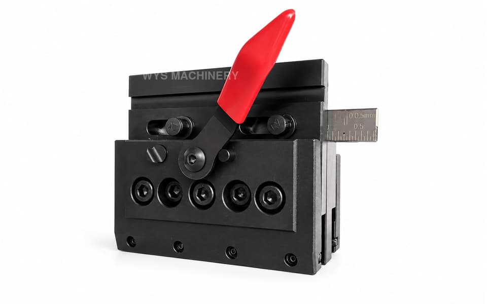
KJ-12-S Compact Double-Sided Press Brake Quick Clamp
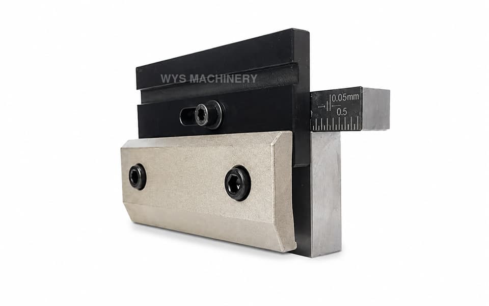
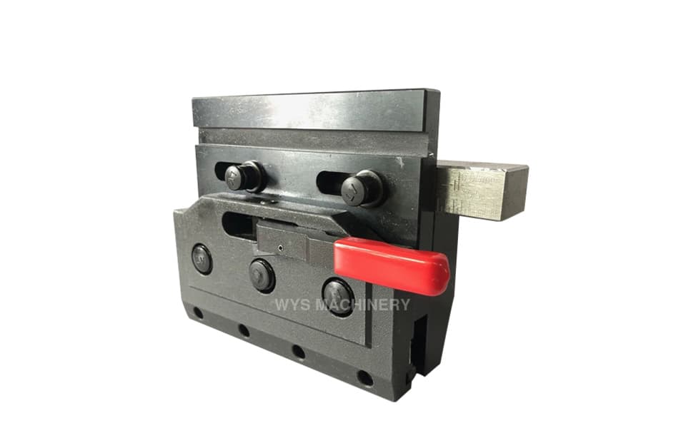
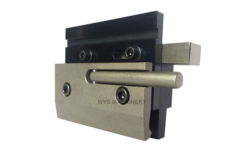
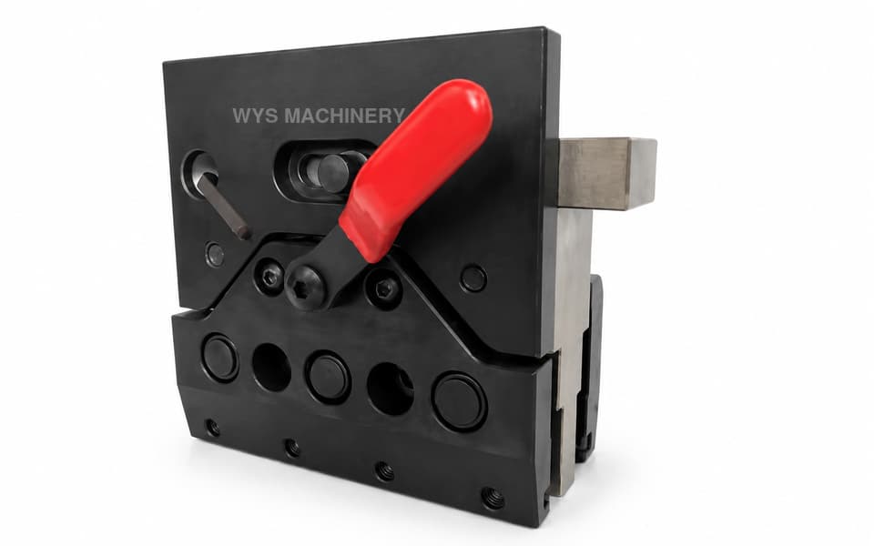
The KJ-12-S is a compact double-sided mechanical press brake quick clamp with a distinctive 100 mm working height. Compatible upper punches can be installed on either clamping face and loaded horizontally from the side. Its front plate is mounted to the locking plate rather than the large tapered wedge, creating a tooling centerline position that differs from the KJ-10-S by 13 mm. Custom configurations and machine-based clamp selection support are available from WYS Machinery.
Please add the quotation and send it to us and get in touch with us immediately
- Global service 24/7
- Lowest price for all products
- Best quality with Production Process
- After-Sale Warranty
- Technical Support
Description
The KJ-12-S Compact Double-Sided Press Brake Quick Clamp is designed for press brake applications requiring a shorter clamping height, double-sided upper tool installation, and a specific tooling centerline position.
Many double-sided press brake clamps use a working height of approximately 120 mm. In comparison, the KJ-12-S has a compact working height of 100 mm. This shorter configuration makes it suitable for machines and tooling arrangements where the available daylight, shut height, ram interface, or required punch position does not suit a taller clamp.
Compatible upper punches can be installed on either side of the KJ-12-S. The double-sided clamping structure allows tooling to be arranged in different directions according to the press brake configuration and bending requirements. Punches are loaded horizontally from the side of the clamping line.
A defining structural feature of the KJ-12-S is the connection between its front clamping plate and locking mechanism. On this model, the front plate is mounted to the locking plate. By comparison, the front plate of the KJ-10-S is mounted to the large tapered wedge. This difference changes the position of the upper tooling centerline.
The tooling centerline of the KJ-12-S differs from that of the KJ-10-S by 13 mm. Therefore, these two clamps should not be selected or interchanged based only on their general appearance. The press brake bending axis, ram connection, lower die centerline, upper punch position, and machine installation dimensions must all be considered.
WYS Machinery offers customized quick clamps and technical selection support. If customers are unsure which model is suitable, they can provide their press brake information, mounting dimensions, existing clamp drawings, and upper tooling profiles. Our technical team will evaluate the machine interface and recommend a suitable clamping solution.
Key Features
- Compact double-sided mechanical quick clamp
- Distinctive 100 mm working height
- Shorter than many common 120 mm double-sided clamps
- Front and rear upper tool clamping faces
- Supports tooling installed in different directions
- Compatible punches are loaded horizontally from the side
- Front plate mounted directly to the locking plate
- Different internal structure from the KJ-10-S
- Tooling centerline differs from the KJ-10-S by 13 mm
- Mechanical lever-operated locking and releasing
- No hydraulic, pneumatic, or electrical power required
- Main components manufactured from 45# carbon steel
- Precision-machined mounting and locating surfaces
- Custom dimensions and interfaces available
- Machine-based product selection support from WYS Machinery
Technical Specifications
| Item | Specification |
|---|---|
| Model | KJ-12-S |
| Product Type | Double-Sided Press Brake Quick Clamp |
| Clamping Structure | Mechanical |
| Number of Clamping Faces | Two |
| Tool Mounting Positions | Front and Rear |
| Tool Loading Method | Horizontal Side Loading |
| Vertical Tool Loading | Not Supported |
| Operating Method | Manual Lever Operation |
| Working Height | 100 mm |
| Front Plate Connection | Mounted to the Locking Plate |
| Centerline Difference vs. KJ-10-S | 13 mm |
| Main Material | 45# Carbon Steel |
| Key Dimensional Tolerance | ±0.02 mm |
| Parallelism | ≤0.02 mm |
| Perpendicularity | ≤0.02 mm |
| Customization | Available |
| External Power Required | No |
Compact 100 mm Working Height
The 100 mm working height is one of the most important characteristics of the KJ-12-S. Many conventional double-sided quick clamps use a height of approximately 120 mm, but that configuration is not suitable for every press brake.
A shorter clamp changes the relationship between the ram, upper punch, lower die, machine daylight, and available bending stroke. The compact KJ-12-S can be considered for machines requiring:
- A shorter upper clamping assembly
- Additional usable open height
- A different press brake shut-height configuration
- A specific upper punch position
- Replacement of an existing 100 mm clamp
- A customized tooling centerline arrangement
Working height alone cannot determine compatibility. The complete mounting and bending geometry must also be checked.
Double-Sided Upper Tool Installation
The KJ-12-S provides clamping interfaces on both sides. Compatible upper punches can be mounted on the front or rear face according to the required tooling orientation and bending process.
The double-sided configuration provides greater flexibility when planning upper tooling arrangements. Where supported by the press brake layout, operators can prepare different punch profiles or tooling directions for different bending operations, helping reduce repeated complete tool changes.
Horizontal Side-Loading Design
Compatible upper punches must be inserted horizontally from the side of the KJ-12-S. After the tool reaches the required position, the mechanical lever activates the clamping structure and locks the punch in place.
This model does not support direct vertical punch insertion or downward removal. Sufficient side clearance must therefore be available for tooling installation and replacement.
The upper punch tang profile, safety interface, tool length, and clamping dimensions should be verified before ordering.
Locking Plate-Mounted Front Panel
The front plate of the KJ-12-S is mounted to the locking plate. This connection differs from the KJ-10-S, where the front plate is mounted to the large tapered wedge.
Although the two products share certain external characteristics, the different internal mounting arrangement changes the position of the clamping interface and tooling centerline.
This design detail is important when replacing an existing clamp or configuring upper tooling for a specific press brake. Selecting the wrong centerline can cause the punch to be misaligned with the lower die or machine bending axis.
13 mm Tooling Centerline Difference
The centerline position of the KJ-12-S differs from that of the KJ-10-S by 13 mm. This value should be considered when evaluating machine compatibility, upper punch alignment, and lower die positioning.
The 13 mm difference does not mean that one model is universally better than the other. Each model is designed for a different installation geometry. The correct choice depends on:
- Press brake ram dimensions
- Machine bending axis
- Ram clamping interface
- Upper punch centerline
- Lower die centerline
- Existing clamp configuration
- Required working height
- Available front and rear clearance
Customers should avoid replacing one model with the other without checking these dimensions.
Mechanical Clamping Operation
The KJ-12-S uses a manual mechanical lever to lock and release compatible press brake punches. It does not require hydraulic pressure, compressed air, an electrical control unit, or an additional power source.
The straightforward mechanical structure offers convenient operation and maintenance while reducing the repetitive screw-tightening work associated with conventional press brake clamps.
Precision and Manufacturing Quality
Critical mounting, clamping, and locating surfaces are precision-machined to support stable installation and repeatable punch positioning.
Key dimensional tolerances are controlled within ±0.02 mm. Parallelism and perpendicularity are maintained within 0.02 mm to help align the upper punch with the press brake ram, bending axis, and lower die.
The main components are manufactured from 45# carbon steel, providing the strength and rigidity required for regular mechanical clamping and frequent tooling changes.
Typical Applications
- CNC and conventional hydraulic press brakes
- Press brakes requiring a 100 mm clamp working height
- Compact upper tool clamping assemblies
- Double-sided press brake tooling arrangements
- Side-loaded upper punches
- Segmented and full-length press brake tooling
- Replacement of compatible 100 mm quick clamps
- Applications requiring a specific tooling centerline
- High-mix and small-batch sheet metal production
- Electrical cabinet and enclosure manufacturing
- Metal doors, panels, and equipment housings
- HVAC and ventilation component fabrication
- Carbon steel and stainless steel bending
- Customized press brake clamping system upgrades
How to Select the Correct Quick Clamp
A press brake quick clamp should not be selected solely by product appearance, working height, or handle style. Even visually similar clamps may have different mounting interfaces, centerline positions, loading methods, and upper tooling compatibility.
Customers who are unsure which quick clamp to choose can provide:
- Press brake brand and model
- Ram cross-section drawing
- Existing clamp photographs
- Existing clamp dimensions
- Mounting-hole locations
- Upper punch tang profile
- Lower die centerline information
- Required working height
- Tool-loading direction
- Current bending center position
WYS Machinery will evaluate this information and recommend a suitable quick clamp for the customer’s press brake and tooling system.
Custom Press Brake Quick Clamps
All WYS Machinery quick clamps and standard press brake clamps support customization. Depending on the machine and tooling requirements, available customization can include:
- Working height
- Clamp width
- Tooling centerline position
- Front and rear clamping configuration
- Ram mounting interface
- Mounting-hole positions
- Upper punch tang interface
- Side-loading or vertical-loading structure
- Handle and operating mechanism
- Surface treatment
- Special replacement and retrofit configurations
Customers can send machine drawings, tooling profiles, product requirements, or an existing clamp sample. Our technical team can then recommend or design a clamping solution suited to the actual installation conditions.