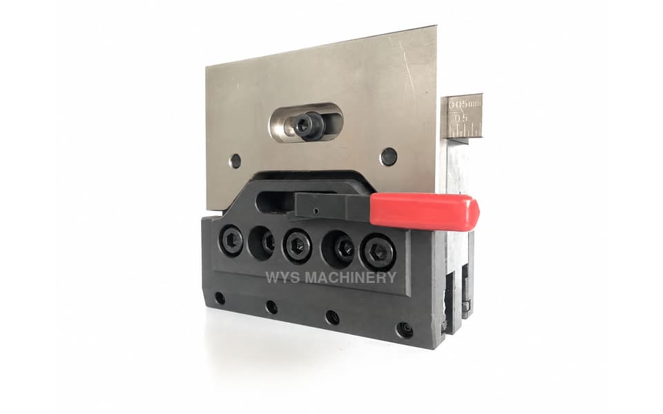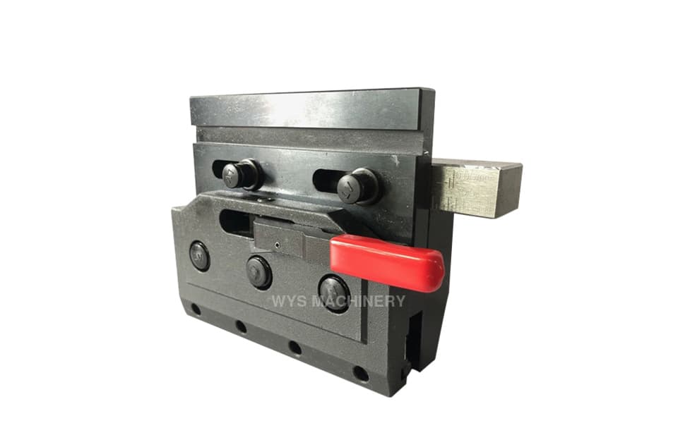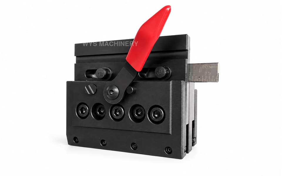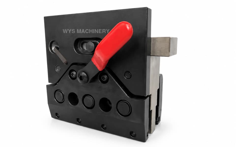
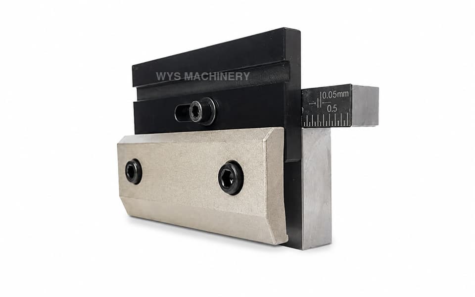
PJ-B Grooved Screw-Type Press Brake Upper Tool Clamp
The PJ-B is a standard mechanical press brake upper tool clamp with an 85 mm working height and 150 mm width. The upper punch is secured by manually tightening the front clamping screws rather than operating a quick-release handle. A mounting groove at the top allows the press brake ram pressure plate to grip and secure the clamp to the machine.
Please add the quotation and send it to us and get in touch with us immediately
- Global service 24/7
- Lowest price for all products
- Best quality with Production Process
- After-Sale Warranty
- Technical Support
Description
The PJ-B Grooved Screw-Type Press Brake Upper Tool Clamp is a conventional mechanical clamping solution designed to connect compatible upper punches to the press brake ram.
Unlike a lever-operated quick clamp, the PJ-B secures the upper punch by means of manually tightened clamping screws. As the screws are tightened, the front clamping plate applies pressure to the punch tang and holds the upper tooling securely in position.
The key structural difference between the PJ-B and PJ-C is the upper mounting interface. The PJ-B has a dedicated clamping groove at the top. During installation, the pressure plate on the press brake ram engages with this groove and clamps the PJ-B firmly to the machine.
This grooved mounting structure provides a defined gripping area between the clamp and ram pressure plate. It can be used as a replacement or customized clamping solution where the press brake connection is designed for this type of mounting groove.
The PJ-B has an effective working height of 85 mm and a width of 150 mm. Its compact height makes it suitable for press brakes and tooling arrangements requiring a shorter upper clamping assembly.
The main components are manufactured from 45# carbon steel. Critical mounting, locating, and clamping surfaces are precision-machined to support stable punch positioning and accurate alignment with the lower die.
Key Features
- Standard mechanical press brake upper tool clamp
- Screw-type upper punch locking
- Upper tool secured by tightening front clamping screws
- No press-down or rotary quick-release handle
- Dedicated upper clamping groove
- Mounted to the press brake ram using a pressure plate
- Defined pressure-plate gripping interface
- 85 mm working height
- 150 mm clamp width
- Main components manufactured from 45# carbon steel
- No hydraulic, pneumatic, or electrical power required
- Simple and rigid mechanical structure
- Precision-machined mounting and clamping surfaces
- Suitable for longer production runs with fewer tool changes
- Custom mounting dimensions and interfaces available
Technical Specifications
| Item | Specification |
|---|---|
| Model | PJ-B |
| Product Type | Standard Press Brake Upper Tool Clamp |
| Clamp Category | Conventional Clamp |
| Clamping Structure | Mechanical |
| Upper Tool Clamping Method | Screw Tightening |
| Operating Method | Manual Bolt Tightening |
| Quick-Release Handle | No |
| Upper Mounting Interface | Clamping Groove |
| Clamp-to-Ram Connection | Ram Pressure Plate |
| Working Height | 85 mm |
| Clamp Width | 150 mm |
| Main Material | 45# Carbon Steel |
| Key Dimensional Tolerance | ±0.02 mm |
| Parallelism | ≤0.02 mm |
| Perpendicularity | ≤0.02 mm |
| External Power Required | No |
| Customization | Available |
Grooved Upper Mounting Interface
The upper section of the PJ-B incorporates a clamping groove designed to engage with the press brake ram pressure plate. When the pressure plate is tightened, it grips the groove and secures the complete upper tool clamp to the machine.
This mounting method creates a defined mechanical connection between the press brake ram and PJ-B clamp. The following dimensions must match the machine:
- Groove height and depth
- Groove position
- Ram pressure plate thickness
- Available gripping area
- Mounting-hole positions
- Working height
- Tooling centerline
The presence of a similar-looking groove does not automatically guarantee compatibility. Accurate dimensions or drawings should be checked before ordering.
Screw-Type Upper Tool Clamping
After the PJ-B has been secured to the press brake ram, the compatible upper punch is positioned inside the lower clamping interface. The operator then tightens the front screws using an appropriate hand tool.
The clamping screws move or load the front plate against the punch tang, creating the mechanical pressure required to hold the upper tool securely.
The screws should be tightened gradually and evenly. Uneven tightening may create inconsistent pressure or affect punch alignment along the press brake working length.
To remove the tool, the operator supports the punch, loosens the screws evenly, and withdraws the upper tool according to the machine and tooling configuration.
Difference Between PJ-B and PJ-C
Both PJ-B and PJ-C are standard screw-type press brake clamps. Neither model uses a quick-release lever to secure the upper punch. Their primary difference is the way in which the clamp is connected to the press brake ram.
| Feature | PJ-B | PJ-C |
|---|---|---|
| Clamp Type | Standard Screw-Type Clamp | Standard Screw-Type Clamp |
| Working Height | 85 mm | 85 mm |
| Clamp Width | 150 mm | 150 mm |
| Punch Locking Method | Front Clamping Screws | Front Clamping Screws |
| Upper Mounting Groove | Yes | No |
| Ram Connection | Pressure Plate Engages the Groove | Different Direct Mounting Interface |
| Quick-Release Handle | No | No |
The correct model should be selected according to the press brake ram and pressure plate structure rather than appearance alone.
Difference Between PJ-B and a Quick Clamp
The PJ-B is a conventional clamp, not a press brake quick clamp.
| Feature | PJ-B Standard Clamp | Mechanical Quick Clamp |
|---|---|---|
| Upper Tool Locking | Tighten Screws | Operate a Lever or Handle |
| Tool Release | Loosen Screws | Move Quick-Release Handle |
| Tool Change Speed | Conventional | Faster |
| Main Mechanism | Screw and Clamping Plate | Lever, Cam or Wedge |
| External Power | Not Required | Not Required |
| Typical Use | Less Frequent Tool Changes | Frequent Tool Changes |
The PJ-B is suitable where stable screw clamping and simple construction are more important than the fastest possible tool-changing speed.
Compact 85 mm Working Height
The 85 mm working height makes the PJ-B more compact than many taller upper tool holders. This height can be useful when the press brake requires:
- A shorter upper clamping assembly
- Additional usable open height
- A specific machine shut-height configuration
- Replacement of a compatible 85 mm clamp
- A particular upper punch centerline
- A customized ram-to-tool connection
The machine stroke, daylight, punch height, die height, and bending centerline should all be considered before confirming the clamp height.
Advantages of the PJ-B Standard Clamp
- Simple mechanical clamping principle
- Stable screw-generated locking force
- Defined ram pressure plate mounting groove
- No external power source
- No hydraulic or pneumatic components
- Straightforward inspection and maintenance
- Suitable for tooling kept in place for longer runs
- Practical for conventional press brake configurations
- Customizable for different ram and tooling interfaces
Precision and Manufacturing Quality
Critical mounting, locating, and clamping surfaces of the PJ-B are precision-machined to support accurate installation.
Key dimensional tolerances are controlled within ±0.02 mm. Parallelism and perpendicularity are maintained within 0.02 mm to help align the press brake ram, upper punch, and lower die.
The main components are manufactured from 45# carbon steel, providing the strength and structural rigidity required for repeated screw tightening and regular press brake operation.
Typical Applications
- CNC and conventional hydraulic press brakes
- Grooved press brake clamp mounting systems
- Press brake ram pressure plate connections
- Standard upper tool clamping
- Screw-clamped press brake punches
- Full-length and segmented upper tooling
- Long production runs with fewer tooling changes
- Electrical cabinet and enclosure manufacturing
- Metal doors, panels, and machine housings
- HVAC and ventilation component fabrication
- Carbon steel and stainless steel sheet bending
- Replacement of compatible grooved clamps
- Conventional press brake tooling system upgrades
- Customized upper punch holder applications
Installation and Maintenance
Before installation, the upper mounting groove and press brake ram pressure plate should be inspected for damage, burrs, contamination, or dimensional mismatch.
During operation:
- Ensure the pressure plate fully engages the upper groove
- Tighten the ram connection evenly
- Support the upper punch before loosening the front screws
- Tighten the punch clamping screws gradually and evenly
- Inspect the clamping threads regularly
- Check the front plate for uneven wear
- Confirm upper and lower tool alignment
- Replace damaged screws before further operation
The correct tightening torque depends on the screw size, material, clamp design, and intended working conditions.
Compatibility and Product Selection
The PJ-B should not be selected solely according to its 85 mm working height, 150 mm width, or external appearance. The upper mounting groove must match the press brake ram pressure plate.
Customers should provide:
- Press brake brand and model
- Ram cross-section drawing
- Pressure plate dimensions
- Mounting groove dimensions
- Existing clamp measurements
- Upper punch tang profile
- Tooling centerline position
- Mounting-hole locations
- Clear photographs of the current installation
If customers are unsure whether the PJ-B, PJ-C, or a quick clamp is appropriate, WYS Machinery can evaluate the machine interface and tool-changing requirements before recommending a suitable model.
Custom Press Brake Clamps
All WYS Machinery quick clamps and standard press brake clamps support customization. Available customized features include:
- Working height
- Clamp width
- Upper mounting groove
- Groove position and dimensions
- Ram pressure plate interface
- Mounting-hole locations
- Tooling centerline
- Upper punch tang interface
- Front clamping plate
- Screw quantity and position
- Surface treatment
- Replacement and retrofit configurations
Customers can provide machine drawings, upper punch profiles, existing clamp samples, or installation photographs. WYS Machinery can then recommend or develop a suitable press brake upper tool clamping solution.