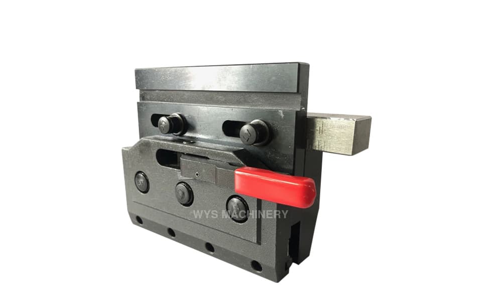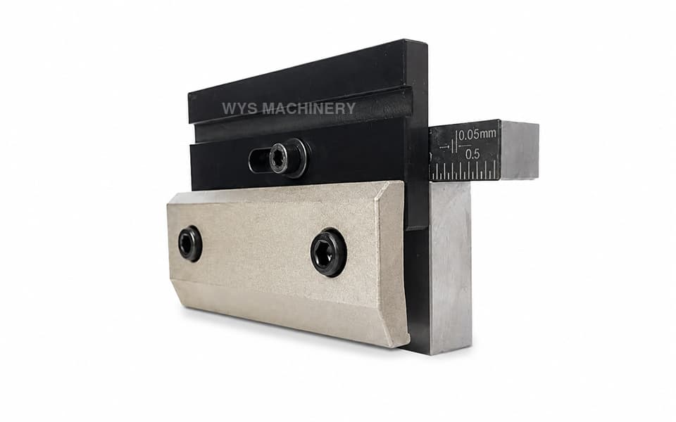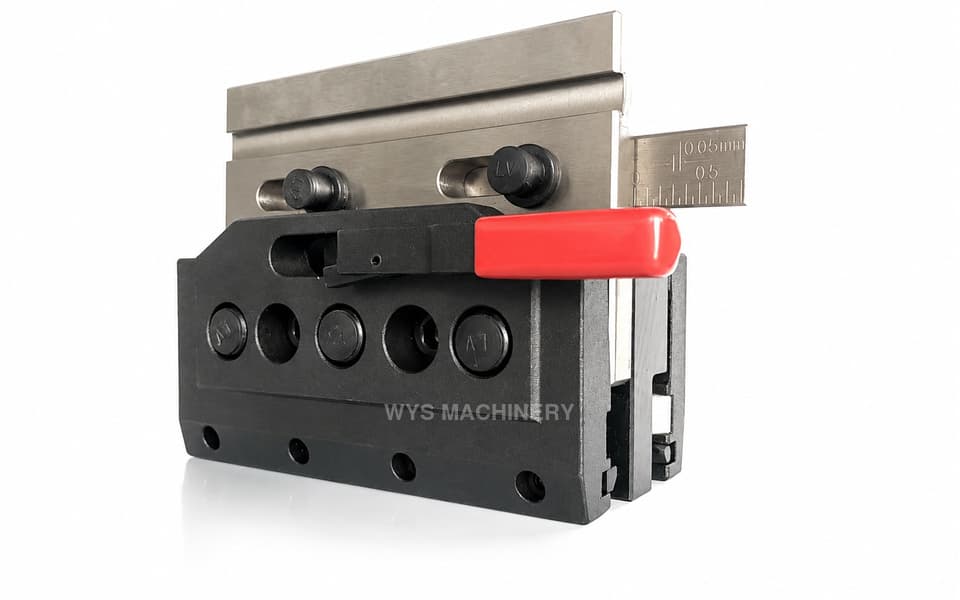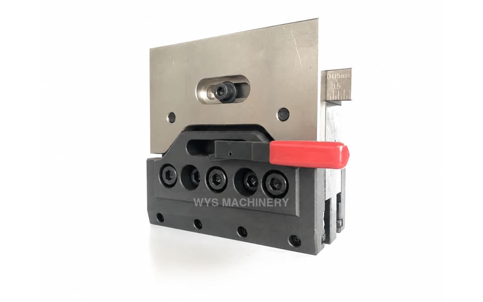
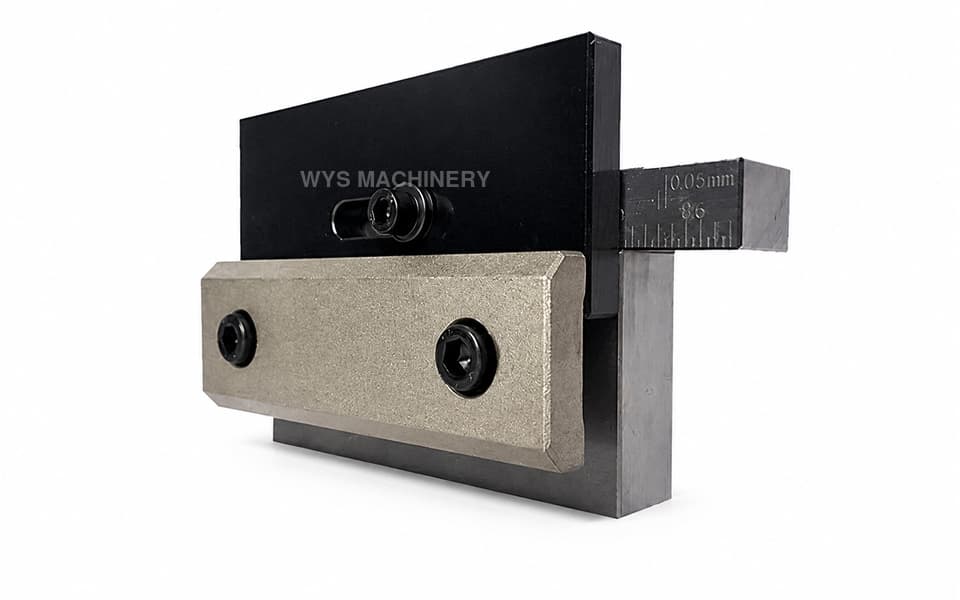
PJ-C Screw-Type Press Brake Upper Tool Clamp
The PJ-C is a standard mechanical press brake upper tool clamp that secures the punch by tightening clamping screws. Unlike a quick clamp operated by a lever or rotary handle, this conventional clamp applies locking force through manually tightened bolts. It has an 85 mm working height, 150 mm width, and a simple, rigid structure suitable for press brakes that do not require frequent upper tool changes.
Please add the quotation and send it to us and get in touch with us immediately
- Global service 24/7
- Lowest price for all products
- Best quality with Production Process
- After-Sale Warranty
- Technical Support
Description
The PJ-C Screw-Type Press Brake Upper Tool Clamp is a conventional mechanical clamping solution designed to connect and secure compatible upper punches to the press brake ram.
Unlike lever-operated quick clamps, the PJ-C does not use a press-down or rotary handle to lock the tooling. The operator tightens the front clamping screws using a suitable tool, causing the clamping plate to apply pressure to the upper punch tang and hold it securely in position.
This traditional screw-clamping structure is straightforward, reliable, and easy to maintain. It is particularly suitable for press brake applications where the upper tooling remains installed for longer production runs and frequent rapid tool changes are not required.
The PJ-C has a working height of 85 mm and a clamp width of 150 mm. Its compact height can be useful for press brakes where the available machine daylight, shut height, or existing upper tool configuration requires a shorter clamping assembly.
The primary components are manufactured from 45# carbon steel. Critical mounting, clamping, and locating surfaces are precision-machined to support stable punch positioning and reliable alignment between the upper tool and lower die.
WYS Machinery can customize the working height, width, mounting dimensions, hole positions, and upper tool interface according to the customer’s press brake and tooling system.
Key Features
- Standard mechanical press brake upper tool clamp
- Screw-type punch clamping structure
- Upper tool secured by manually tightening clamping bolts
- No press-down or rotary quick-clamp handle
- Simple and rigid mechanical construction
- Suitable for tooling that does not require frequent replacement
- 85 mm working height
- 150 mm clamp width
- Main components manufactured from 45# carbon steel
- No hydraulic, pneumatic, or electrical power required
- Precision-machined mounting and clamping surfaces
- Convenient inspection and mechanical maintenance
- Custom mounting interfaces and dimensions available
- Suitable for new press brakes, replacements, and machine upgrades
Technical Specifications
| Item | Specification |
|---|---|
| Model | PJ-C |
| Product Type | Standard Press Brake Upper Tool Clamp |
| Clamp Category | Conventional Clamp |
| Clamping Structure | Mechanical |
| Clamping Method | Screw Tightening |
| Operating Method | Manual Bolt Tightening |
| Quick-Release Handle | No |
| Application | Press Brake Upper Punch Clamping |
| Working Height | 85 mm |
| Clamp Width | 150 mm |
| Main Material | 45# Carbon Steel |
| Key Dimensional Tolerance | ±0.02 mm |
| Parallelism | ≤0.02 mm |
| Perpendicularity | ≤0.02 mm |
| External Power Required | No |
| Customization | Available |
Screw-Type Clamping Operation
The compatible upper punch is positioned inside the clamping interface. The operator then tightens the front screws using the appropriate hand tool.
As the screws are tightened, the front clamping plate moves toward the punch tang and applies mechanical pressure across the clamping interface. The screws should be tightened evenly to maintain consistent pressure and prevent the punch from being pulled out of alignment.
To remove or replace the upper tool, the operator supports the punch, loosens the clamping screws, and withdraws the tool according to the machine and tooling configuration.
Difference Between a Standard Clamp and a Quick Clamp
The PJ-C is a standard screw-type clamp rather than a press brake quick clamp. The main difference is the way in which the upper tool is locked and released.
| Feature | PJ-C Standard Clamp | Mechanical Quick Clamp |
|---|---|---|
| Locking Method | Tightening Screws | Pressing or Rotating a Handle |
| Tool Release | Loosen Screws Manually | Operate Quick-Release Lever |
| External Power | Not Required | Not Required |
| Tool Change Speed | Conventional | Faster |
| Structure | Simple Screw Clamping | Lever or Cam Mechanism |
| Best Suited For | Longer Runs and Less Frequent Changes | Frequent Tool Changeovers |
A standard clamp is appropriate where straightforward construction, stable mechanical locking, and uncomplicated maintenance are more important than the fastest possible tool-changing speed.
Compact 85 mm Working Height
The PJ-C has an effective working height of 85 mm. This compact configuration changes the installed relationship between the press brake ram and upper punch and can preserve more of the machine’s available open height.
It may be suitable for:
- Press brakes originally designed for a shorter clamp
- Applications requiring a compact upper clamping assembly
- Machines with limited daylight
- Replacement of compatible 85 mm clamps
- Tooling arrangements requiring a specific shut height
- Customized press brake upper tool installations
Working height alone cannot confirm compatibility. The ram interface, punch centerline, mounting dimensions, and lower die position must also be checked.
Advantages of a Conventional Mechanical Clamp
Although a screw-type clamp does not provide the same tool-changing speed as a quick clamp, it offers several practical advantages:
- Straightforward mechanical construction
- Stable screw-generated clamping force
- No hydraulic or pneumatic power unit
- No lever or cam mechanism to adjust
- Convenient inspection and maintenance
- Suitable for longer production runs
- Practical for tooling changed only occasionally
- Cost-effective for conventional press brake configurations
- Adaptable to customized machine interfaces
Precision and Manufacturing Quality
Critical mounting, clamping, and positioning surfaces are precision-machined to support accurate upper punch installation.
Key dimensional tolerances are controlled within ±0.02 mm. Parallelism and perpendicularity are maintained within 0.02 mm to help align the press brake ram, upper punch, and lower die.
The main components are manufactured from 45# carbon steel, providing the rigidity and mechanical strength required for repeated screw tightening and regular press brake operation.
Typical Applications
- CNC and conventional hydraulic press brakes
- Standard press brake upper tool clamping
- Screw-clamped press brake punches
- Conventional punch holder systems
- Full-length and segmented upper tooling
- Long production runs with fewer tooling changes
- Electrical cabinet and enclosure manufacturing
- Metal doors, panels, and equipment housings
- HVAC and ventilation component fabrication
- Carbon steel and stainless steel sheet bending
- Replacement of compatible standard clamps
- Press brake tooling system repairs and upgrades
- Customized upper tool clamping applications
Installation and Operating Recommendations
Before installing or removing an upper punch, the machine should be stopped and the tool must be adequately supported. Clamping screws should be tightened gradually and evenly rather than fully tightening one screw before the others.
The recommended tightening torque depends on the screw specification, clamp structure, punch tang, and working conditions. Excessive torque may damage the screws or clamping plate, while insufficient torque may allow the upper tool to move.
The following items should be inspected regularly:
- Clamping screw condition
- Thread wear or damage
- Front plate contact surface
- Upper punch tang condition
- Mounting bolts and slots
- Tool alignment
- Clamping pressure consistency
- Ram and lower die centerline
Compatibility and Product Selection
Press brake clamp dimensions and upper tooling interfaces vary among machine models. Customers should not select the PJ-C solely according to its external appearance, 85 mm working height, or 150 mm width.
Before ordering, customers should provide:
- Press brake brand and model
- Ram cross-section drawing
- Existing clamp dimensions
- Mounting-hole positions
- Upper punch tang profile
- Required tooling centerline
- Tool installation direction
- Photographs of the existing machine interface
If the customer is unsure whether a standard clamp or quick clamp is more suitable, WYS Machinery can evaluate the press brake, tooling-change frequency, production process, and mounting dimensions before recommending an appropriate solution.
Custom Press Brake Clamps
All WYS Machinery quick clamps and conventional press brake clamps support customization. Available options can include:
- Working height
- Clamp width
- Mounting-hole positions
- Ram connection interface
- Upper punch clamping profile
- Tooling centerline
- Clamping plate dimensions
- Screw quantity and position
- Surface treatment
- Replacement and retrofit configurations
Customers can provide machine drawings, upper punch profiles, existing clamp samples, or clear installation photographs. WYS Machinery can then recommend or design a suitable upper tool clamping solution.