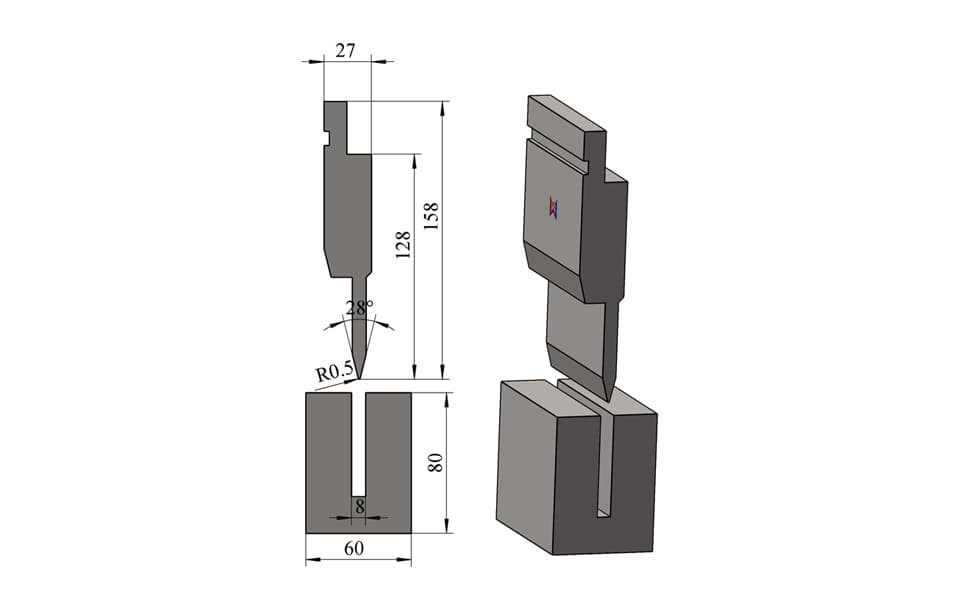
U-Groove Two-Stage Hemming Die for Thin Sheet Metal
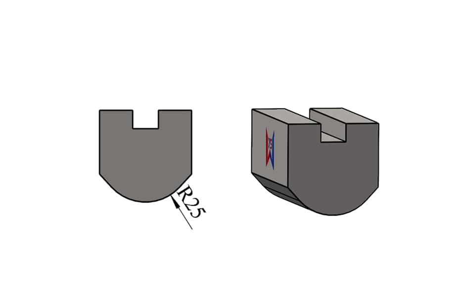
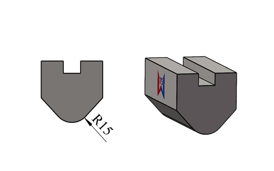
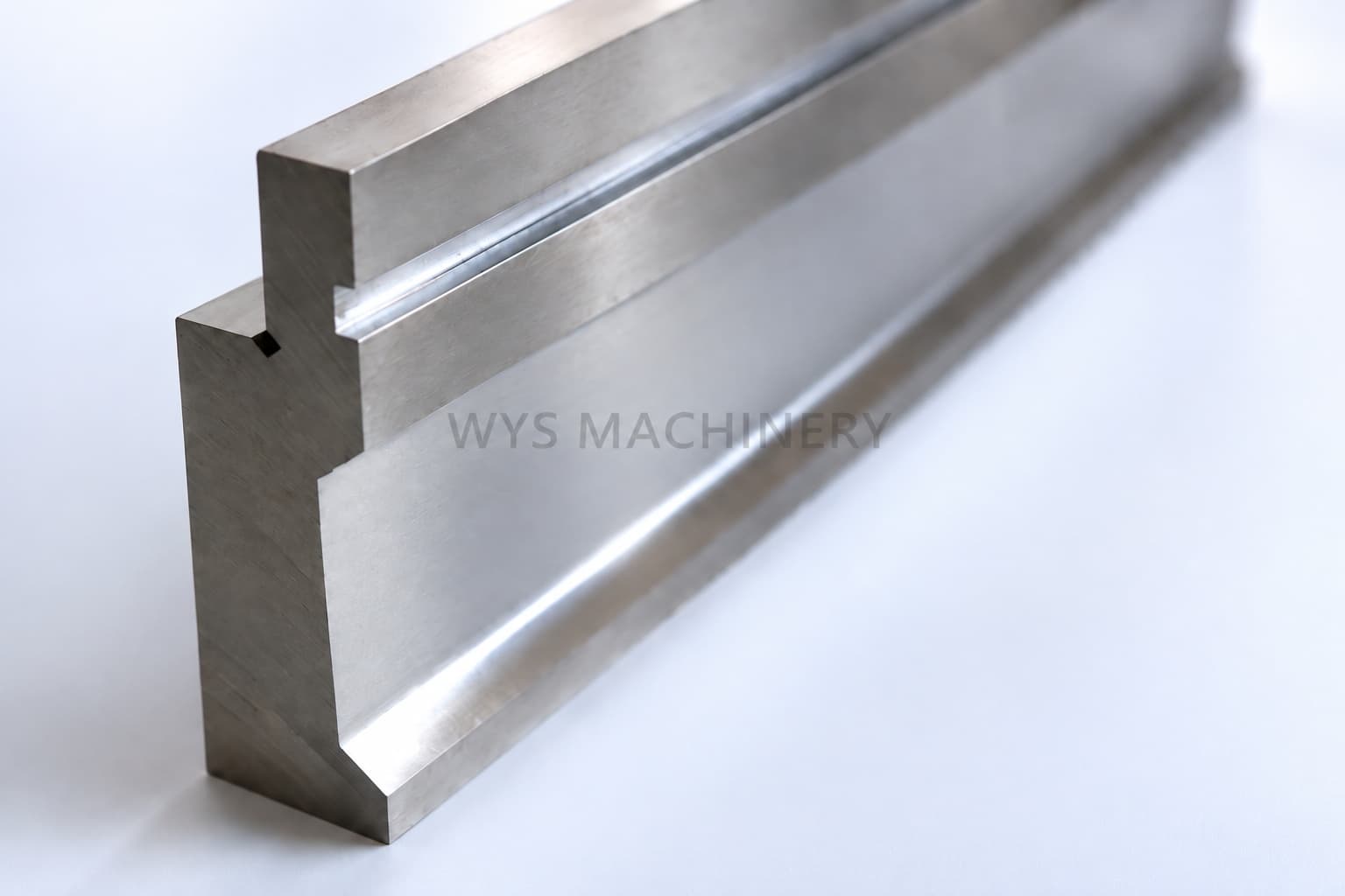
A custom U-groove press brake hemming die designed to perform both the 28° acute pre-bending operation and the final flattening operation in the same die groove. Unlike conventional spring-loaded or pneumatic hemming tools, this design uses a fixed U-shaped die opening without an additional moving flattening mechanism. The illustrated tooling is designed for 1.0 mm sheet metal, with this structure typically suitable for thin sheets below approximately 1.5 mm, depending on material properties, hem geometry and application requirements. Maximum tooling load: 100 ton/m.
Please add the quotation and send it to us and get in touch with us immediately
- Global service 24/7
- Lowest price for all products
- Best quality with Production Process
- After-Sale Warranty
- Technical Support
Description
U-Groove Two-Stage Hemming Die – Pre-Bending and Flattening in the Same Groove
Hemming is normally completed in two stages. The sheet is first bent to an acute angle, often approximately 27–30°, and then compressed in a second operation to close or flatten the folded edge. Many conventional systems use a separate flattening surface or an integrated spring-loaded mechanism to accomplish the second stage.
This special U-groove hemming die uses a different principle.
The first operation forms the sheet to approximately 28°, while the second operation places the pre-bent workpiece back into the same U-shaped groove for final flattening.
Therefore, both stages are completed with the same punch-and-die set and the same die opening.
This provides a simple and compact solution for selected thin-sheet hemming applications, especially where a conventional spring hemming die or pneumatic hemming tool is not required.
How the Two-Stage U-Groove Hemming Process Works
First Operation – 28° Acute Pre-Bending
During the first bending operation, the 28° punch with R0.5 tip radius enters the U-shaped lower die groove and forms the required acute bend.
This creates the preliminary geometry necessary for the following flattening operation.
Second Operation – Flattening the Pre-Bent Sheet
After the first bend, the workpiece is repositioned for the second operation.
Instead of moving the sheet to another flattening station, the already bent section is placed back into the same U-groove die opening.
The press brake then closes the pre-bent profile further until the required flattened or hemmed shape is obtained.
This is the key difference between this tooling and many conventional press brake hemming systems.
Key Advantages
Same Groove for Both Operations
Both the 28° pre-bending and final flattening are performed using the same lower-die groove, reducing the need for a separate flattening station.
No Spring Mechanism
Unlike many spring-loaded hemming tools, this design does not depend on internal compression springs to transition between bending and flattening.
No Pneumatic Mechanism
There is also no pneumatic cylinder or compressed-air system involved in the hemming operation.
The tooling therefore has a comparatively straightforward mechanical structure.
Designed for Thin Sheet Metal
This tooling concept is particularly suitable for thin sheet hemming.
The tooling shown here was designed for approximately:
Sheet thickness: 1.0 mm
For this type of structure, we normally recommend applications below approximately 1.5 mm, subject to actual material strength, ductility, bending length and required hem geometry.
High Tooling Load Capacity
The tooling shown is rated at:
100 ton/m
Actual permissible working load should always be checked according to tooling length, press brake configuration, material and application conditions.
Technical Specifications
| Parameter | Specification |
|---|---|
| Tool Type | U-Groove Two-Stage Hemming Die |
| Application | Pre-Bending + Flattening / Hemming |
| Pre-Bending Angle | 28° |
| Punch Tip Radius | R0.5 |
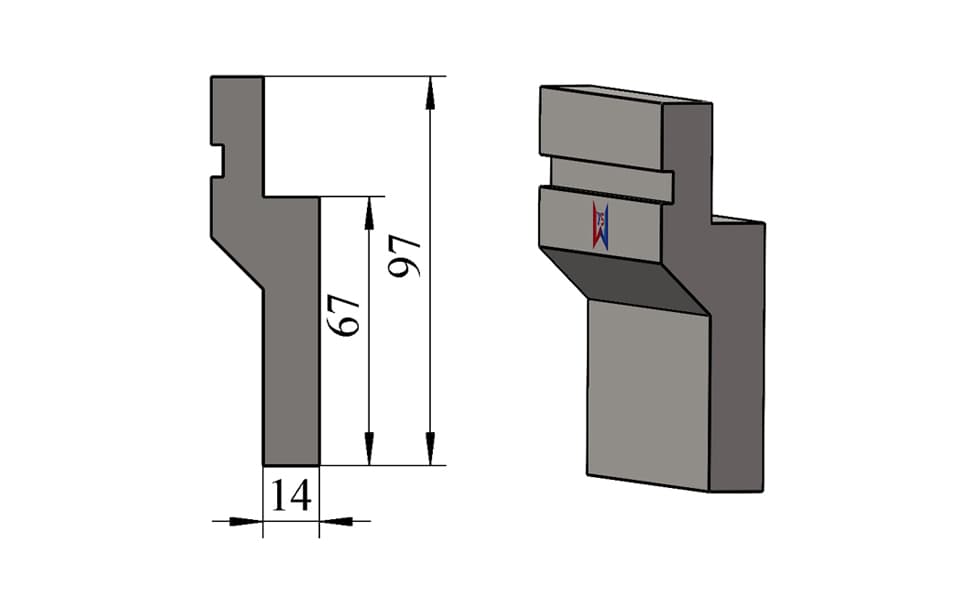
| Punch Total Height | 158 mm |
| Punch Effective Height | 128 mm |
| Punch Width | 27 mm |
| Lower Die Height | 80 mm |
| Lower Die Width | 60 mm |
| U-Groove Width | 8 mm |
| Example Sheet Thickness | 1.0 mm |
| Typical Recommended Thickness | Below approx. 1.5 mm |
| Maximum Load | 100 ton/m |
| Process | Two-stage operation using the same die groove |
| Spring Mechanism | No |
| Pneumatic Mechanism | No |
| Customization | Available |
Comparison with Conventional Hemming Tooling
| Tooling Structure | First Operation | Second Operation | Mechanism |
|---|---|---|---|
| This U-Groove Hemming Die | 28° acute bending | Flattening in the same groove | Fixed tooling structure |
| Conventional Two-Stage Hemming Tool | Acute bending station | Separate flattening station | Two different working areas |
| Spring-Loaded Hemming Tool | Acute bending | Flattening after spring compression | Spring mechanism |
| Pneumatic Hemming Tool | Acute bending | Controlled flattening | Pneumatic mechanism |
Typical Applications
This U-groove hemming tool can be used for thin-sheet components requiring folded, closed or flattened edges, including:
- Electrical enclosures
- Control cabinets
- Sheet metal covers
- Equipment housings
- Stainless steel sheet components
- Thin steel panels
- Appliance panels
- Decorative sheet metal parts
- Light-gauge sheet metal fabrication
- Custom enclosure and cabinet manufacturing
Hemming itself is commonly used to produce smoother and reinforced sheet edges in products such as enclosures, panels and fabricated sheet-metal components.
Custom Press Brake Hemming Tooling
The Tool Shown Is an Example, Not a Limitation
The tooling shown on this page represents one custom U-groove hemming solution developed for a specific thin-sheet application.
It does not mean that we only manufacture this size, angle, groove geometry or mounting system.
Different sheet materials, thicknesses and product geometries require different hemming-tool configurations.
We can customize:
- Punch angle
- Punch height
- Effective tooling height
- Punch width
- Punch tip radius
- Lower die height
- U-groove width and depth
- Hemming clearance
- Tooling length
- Segmentation
- Load capacity
- Mounting style
- Tooling material
- Heat treatment
- Surface treatment
Press Brake Tooling for Different Machine Systems
The illustrated tool is only one mounting configuration.
According to the customer's press brake and clamping system, we can manufacture compatible custom hemming tooling for different machine and tooling styles, including:
AMADA Type, TRUMPF Type, WILA Type, LVD Type, Bystronic Type and other press brake tooling systems.
For customers using other press brake brands or customized clamping systems, the tooling interface can also be designed according to drawings or tooling samples.
Custom Tooling Design Service
For special bending applications, choosing a tool only from a catalogue is often not enough.
Customers can send us:
- Finished part drawings
- Sheet thickness
- Material grade
- Bend dimensions
- Required hem geometry
- Press brake model
- Tooling interface
- Maximum available press brake tonnage
Our engineering team can evaluate the forming sequence and help design an appropriate custom press brake tooling solution.
For this type of special hemming project, we pay particular attention to:
pre-bending angle, flattening clearance, material springback, sheet thickness, groove geometry, tooling strength and interference between the workpiece and press brake tooling.